SERVICE CAUTIONS
id000000800200
Injury/damage Prevention Precautions
• Depending on the vehicle, the cooling fan may operate suddenly even when the ignition is switched off. Therefore, keep hands and tools away from the cooling fan even if the cooling fan is not operating to prevent injury to personnel or damage to the cooling fan. Always disconnect the negative battery terminal when servicing the cooling fan or parts near the cooling fan.
Protection of the Vehicle
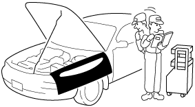
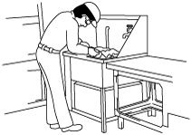
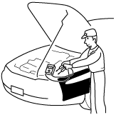
• Always be sure to cover fenders, seats and floor areas before starting work.
Preparation of Tools and Measuring Equipment
• Be sure that all necessary tools and measuring equipment are available before starting any work.
Special Service Tools
• Use special service tools or the equivalent when they are required.
Malfunction Diagnosis System
• Use the Mazda Modular Diagnostic System (M-MDS) for malfunction diagnosis.
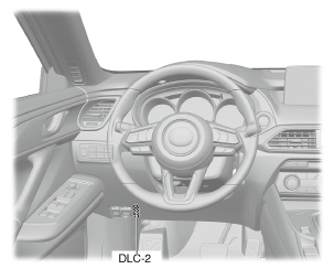
Connection to malfunction diagnosis system
-
• With the ignition switched off, connect the malfunction diagnosis system to the DLC-2 connector shown in the figure.
Oil Leakage Inspection
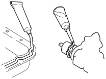
• Use either of the following procedures to identify the type of oil that is leaking:
Using UV light (black light)
1. Remove any oil on the engine or transmission/transaxle.
-
Note
-
• Referring to the fluorescent dye instruction manual, mix the specified amount of dye into the engine oil or transmission/transaxle oil.
2. Pour the fluorescent dye into the engine oil or transmission/transaxle oil.
3. Allow the engine to run for 30 min.
4. Inspect for dye leakage by irradiating with UV light (black light), and identify the type of oil that is leaking.
5. If no dye leakage is found, allow the engine to run for another 30 min. or drive the vehicle then reinspect.
6. Find where the oil is leaking from, then make necessary repairs.
-
Note
-
• To determine whether it is necessary to replace the oil after adding the fluorescent dye, refer to the fluorescent dye instruction manual.
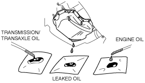
Not using UV light (black light)
1. Gather sample of the leaking oil using an absorbent white tissue.
2. Then, gather some samples of engine and transmission/transaxle oil onto a white cloth or piece of paper.
-
• AT vehicles: ATF
3. Compare the appearance and smell, and identify the type of oil that is leaking.
4. Remove any oil on the engine or transmission/transaxle.
5. Allow the engine to run for 30 min.
6. Check the area where the oil is leaking, then make necessary repairs.
Negative Battery Terminal Disconnection/Connection
Warning
-
• Before removing the SRS air bag system-related parts, always disconnect the negative battery terminal and wait for 1 min. or more to allow the back-up power supply to deplete its stored power. (See
AIR BAG SYSTEM SERVICE WARNINGS.)
Required procedure after negative battery terminal disconnection/connection
|
System name
|
Conditions after disconnecting the negative battery terminal
|
Required procedure
|
Reference
|
|
Before disconnecting negative battery terminal
|
After connecting negative battery terminal
|
|
i-stop system
|
Specified information in the PCM cleared and the i-stop does not operate normally.
|
Verify PID “BATT_SOC” value and record. *1
|
Perform battery condition initial setting (i-stop setting). *2
|
|
|
Tire pressure monitoring system (TPMS)
|
The tire pressure monitoring system detection accuracy decreases.
|
—
|
Perform the tire pressure monitoring system initialization.
|
|
|
Power liftgate (PLG) system
|
—
|
—
|
Fully close the liftgate manually.
|
|
|
Power window system
|
Reset to initial setting and auto-function is disabled.
|
—
|
Perform the power window system initial setting.
|
|
|
Sunroof system
|
Reset to initial setting and function is disabled.
|
—
|
Perform the sunroof system initial setting.
|
|
|
Position memory system
|
Position memory system memory is reset.
|
Verify the setting content.
|
Set the verified content before disconnecting negative battery terminal.
|
—
|
|
Clock and audio
|
Clock display and audio system memory are reset.
|
Verify the setting content.
|
Set the verified content before disconnecting negative battery terminal.
|
—
|
*1 :Because the “BATT_SOC” value before disconnecting the negative battery terminal is required for the battery condition initial setting (i-stop setting), record the “BATT_SOC” value before disconnecting the negative battery terminal.
*2 :For vehicles with i-stop, if the negative battery terminal is disconnected and re-connected, battery condition initial setting (i-stop setting) must be performed.
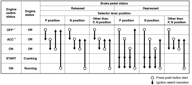
Switch the Power Supply using the Push Button Start and Start the Engine
• By pressing the push button start under the conditions shown in the figure, the ignition can be switched.
*1 :To switch the ignition ACC or OFF from ON (engine on), the vehicle speed must be 5 km/h {3 mph} or less.
Removal of Parts
• While correcting a problem, also try to determine its cause. Begin work only after first learning which parts and sub-components must be removed and disassembled for replacement or repair. After removing the part, plug all holes and ports to prevent foreign material from entering.
Control module configuration (initialization setting)
-
Caution
-
• If the configuration procedure is not completed correctly after replacing a control module in which configuration is required, the system will not operate normally. Therefore, perform the work in accordance with the replacement procedure in the workshop manual.
• If the control module is replaced, and depending on the control module, it may be necessary to write the vehicle specification data to the new control module using the M-MDS. This procedure is for performing the configuration (initial setting).
• There are the following three methods of the configuration procedure for the control module:
-
? Automatic configuration
-
• The main control module (built into instrument cluster) performs configuration of the new control module itself and automatically using the vehicle specification data sent via CAN lines.
? Configuration based on vehicle information read/write data
-
• Reads the vehicle information from the control module prior to replacement, and writes the vehicle information to a new control module.
? Configuration by As-Built data:
-
• Obtains the vehicle specification data when the vehicle is shipped from the factory, and writes the data to a new control module.
• The configuration using As-Built data is used if the vehicle information cannot be read due to a damaged control module which is to be replaced, or if a DTC such as a configuration malfunction is detected.
• If a control module having personalization features is configured using As-Built data, the settings personalized by the customer are initialized (to factory settings). In this case, verify the setting values made by the customer and change the personalized setting values using the “Programmable Parameters” from the M-MDS menu.
• If the module programming menu of the M-MDS (Programmable Module Installation, As-Built, Programmable Parameters) is performed, perform the procedure while the battery monitor icon of the M-MDS is green or gray.
Disassembly
• If the disassembly procedure is complex, requiring many parts to be disassembled, all parts should be marked in a place that will not affect their performance or external appearance, and identified so that reassembly can be performed easily and efficiently.
Inspection During Removal, Disassembly
• When removed, each part should be carefully inspected for malfunction, deformation, damage and other problems.
Arrangement of Parts
• All disassembled parts should be carefully arranged for reassembly.
• Be sure to separate or otherwise identify the parts to be replaced from those that will be reused.
Cleaning of Parts
• All parts to be reused should be carefully and thoroughly cleaned in the appropriate method.
-
Warning
-
• Using compressed air can cause dirt and other particles to fly out causing injury to the eyes. Wear protective eye wear whenever using compressed air.
Reassembly
• Standard values, such as torques and certain adjustments, must be strictly observed in the reassembly of all parts.
• If removed, these parts should be replaced with new ones:
|
Cotter pins
|
Gaskets
|
Locknuts (Nylon nuts)
|
Lock washers
|
|
Oil seals
|
O-rings
|
Spring pins
|
—
|
• Depending on location:
-
? Sealant and gaskets, or both, should be applied to specified locations. When sealant is applied, parts should be installed before sealant hardens to prevent leakage.
? Oil should be applied to the moving components of parts.
? Specified oil or grease should be applied at the prescribed locations (such as oil seals) before reassembly.
Adjustment
• Use suitable gauges and testers when making adjustments.
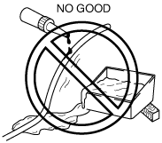
Rubber Parts and Tubing
• Prevent gasoline or oil from getting on rubber parts or tubing.
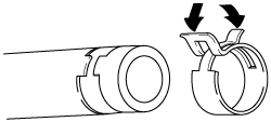
Hose Clamps
• When reinstalling, position the hose clamp in the original location on the hose and squeeze the clamp lightly with large pliers to ensure a good fit.
-
Note
-
• Follow the description in each section because the clamps which are used with the fuel-related system differ from the one indicated above.
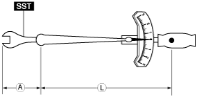
Torque Formulas
• When using a torque wrench-
SST or equivalent combination, the specified torque must be recalculated due to the extra length that the
SST or equivalent adds to the torque wrench. Recalculate the torque by using the following formulas. Choose the formula that applies to you.
|
Torque Unit
|
Formula
|
|
N·m
|
N·m ×[L/(L+A)]
|
|
kgf·m
|
kgf·m ×[L/(L+A)]
|
|
kgf·cm
|
kgf·cm ×[L/(L+A)]
|
|
ft·lbf
|
ft·lbf ×[L/(L+A)]
|
|
in·lbf
|
in·lbf ×[L/(L+A)]
|
A :The length of the SST past the torque wrench drive.
L :The length of the torque wrench.
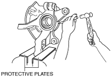
Vise
• When using a vise, put protective plates in the jaws of the vise to prevent damage to parts.
Dynamometer
Cautions on chassis dynamometer use
-
• When inspecting and servicing the powertrain on the dynamometer or speedometer tester, pay attention to the following:
-
Note
-
-
? Place a fan, preferably a vehicle-speed proportional type, in front of the vehicle.
? Make sure the vehicle is in a facility with an exhaust gas ventilation system.
? Keep the rear bumper cool by placing a cooling fan near the exhaust pipe so that the rear bumper does not get deformed by the heat from the exhaust.
? Keep the area around the vehicle uncluttered so that heat does not build up.
? Watch the water temperature gauge and do not overheat the engine.
? Avoid added load to the engine and maintain normal driving conditions as much as possible.
Servicing on vehicles with ABS/DSC
-
• If only the front or rear wheels are rotated using a chassis dynamometer, the DSC HU/CM determines that the ABS/DSC is malfunctioning, detects a DTC, and turns on the related warning light at the same time. (See
DTC TABLE [DSC HU/CM].)
• If the light is turned on, remove the vehicle from the chassis dynamometer and switch the ignition OFF (LOCK). Then switch the ignition ON (engine on) and drive the vehicle at
10 km/h {6.2 mph} or more, and verify that the warning light turns off. The DTC is stored in the memory, therefore erase it by following the ON-BOARD DIAGNOSIS SYSTEM [DSC HU/CM]. (See
CLEARING DTC [DSC HU/CM].)
-
Note
-
Cautions for vehicles with Mazda Radar Cruise Control (MRCC) system/Smart Brake Support (SBS) system/Smart City Brake Support (SCBS) system/Distance Recognition Support System (DRSS)
-
Caution
-
• If a vehicle with the following systems is inspected using a chassis dynamometer, always turn off each system before performing the inspection.
-
? Mazda Radar Cruise Control (MRCC) system
? Smart Brake Support (SBS) system
? Smart City Brake Support (SCBS) system
? Distance Recognition Support System (DRSS)
• If a chassis dynamometer is used without turning off each system, automatic braking will operate and the inspection cannot be performed correctly.
• In the event that a chassis dynamometer is used without turning off each system, take appropriate measures referring to the following as each of the system’s warning lights may be illuminated/flashed and DTCs stored in the memory.
Rotating only front or rear wheels
• If only the front or rear wheels are rotated, the DSC HU/CM will determine that the DSC is malfunctioning. It will also determine that the vehicle control module is malfunctioning and the following warning lights will be illuminated or flashed.
-
? Mazda radar cruise control (MRCC) warning light (amber) is flashed
? Master warning light is illuminated
-
1. If the warning light is illuminated or flashed, remove the vehicle from the chassis dynamometer and switch the ignition off.
2. Switch the ignition back ON and drive the vehicle at 10 km/h or more to verify that the warning light turns off.
3. Because DTCs are stored, clear DTCs according to the memory clearing procedure.
Rotating all four wheels
• If all four wheels are rotated, the cruise control module determines that there is an error in the location information of the object which is detected by the radar sensor. As a result, the vehicle control module determines that a malfunction occurred, illuminates the following warning lights, and displays a message in the instrument cluster.
-
? Master warning light
? Displays “MRCC Inspection Required”, “SCBS Inspection Required”, “SBS Inspection Required”, and “DRSS Inspection Required”
-
1. If a warning light is illuminated and a message is displayed, remove the vehicle from the chassis dynamometer and switch the ignition off.
2. Switch the ignition back ON and verify that the warning light is turned off and the message is cleared.
3. Because DTCs are stored, clear the DTCs according to the memory clearing procedure.
Servicing on Vehicles with Electric Parking Brake
1. For vehicles with the electric parking brake, when the electric parking brake control module detects for 3 s or more that all of the following conditions are met during braking force inspection using a brake tester, the mode is automatically switched to “electric parking brake inspection mode”.
-
• Ignition is switched ON (engine on)
• Selector lever is in N position
• Accelerator and brake pedals are not depressed
• Front wheel speed is 0 km/h {0 mph}
• Rear wheel speed is 2.5—9.0 km/h {1.6—5.5 mph}
-
Note
-
• When the mode is switched to the electric parking brake inspection mode, the electric parking brake warning light turns on.
• The mode may not switch to the electric parking brake inspection mode depending on the specification of the brake tester being used. In this case, depress the parking brake using the normal electric parking brake switch operation and perform the braking force inspection.
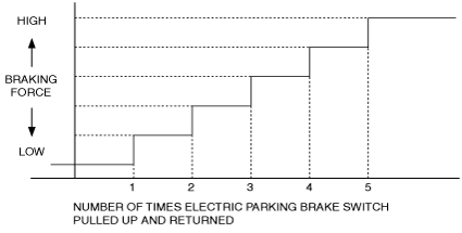
2. When the mode is switched to the electric parking brake inspection mode, the electric parking brake control module increases the braking force of the electric parking brake according to the electric parking brake switch operation as follows.
-
Electric parking brake switch is pulled up and returned for short periods (less than approx. 2 s)
-
• Increase the braking force by one step each time the operation is performed.
-
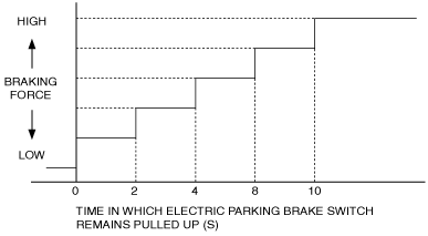
Electric parking brake switch is held pulled up for 2 s or more
-
• Increase the braking force by one step each time
2 s have elapsed.
3. When any of the following conditions is detected, stop the electric parking brake inspection mode.
-
• Selector lever is in position other than N
• Brake pedal is depressed
• Front wheel speed is other than 0 km/h {0 mph}
-
Note
-
• When electric parking brake inspection mode is stopped, the electric parking brake warning light turns off.
Emergency Engine Stop Operation
• While performing an inspection by rotating the wheels using a dynamometer, if the ABS HU/CM (with ABS system) or DSC HU/CM (with DSC system) detects a vehicle speed signal error, the engine cannot be stopped using the push button start. If the engine cannot be stopped using the push button start, perform an emergency stop using the following procedure.
1. Continuously pressing the push button start or quickly pressing it any number of times while the engine is running or the vehicle is being driven will turn the engine off immediately. The ignition switches to ACC.
4WD inspection/service
Speedometer tester measurement
-
Caution
-
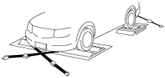
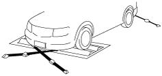
• Install the tension bar (chain wire) to the tie down hook and secure the vehicle to prevent it from rolling and running off.
• Do not accelerate suddenly from a standstill or accelerate/decelerate rapidly.
-
Free roller type
-
1. Align the free rollers with the wheel base and tread, then set them on the floor properly.
2. Drive the vehicle slowly onto the tester roller and free rollers.
3. Start the engine and accelerate gradually to inspect the speedometer.
4. After inspection, decelerate gradually with gentle braking.
-
Propeller shaft removal type
-
1. Remove the propeller shaft.
2. Place the front wheels on the tester roller.
3. Accelerate gradually and inspect the speedometer.
4. After inspection, decelerate gradually with gentle braking.
5. Install the propeller shaft.
Brake tester measurement
1. Place the wheels (front or rear) to be measured on the tester roller.
2. Shift to the N position/neutral.
3. Activate the tester roller and measure braking force. If there is a large amount of brake drag force, the electronic control system coupling may be affected. Jack up all four wheels to eliminate the effect of the coupling and rotate each wheel by hand to verify the rotation condition.
Wheel balancer (on the vehicle balancer)
1. Jack up all four wheels.
2. Support the wheels (front or rear) on the side to be measured (near the wheels) using a wheel balancer sensor stand.
3. Support the wheels on the side not to be measured (near the wheels) using safety stands.
4. Set up the wheel balancer and rotate the wheels using engine drive to measure the wheel balance.
SST
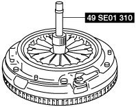
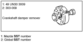
• Some global SST or equivalent are used as SSTs necessary for vehicle repair. Note that these SSTs are marked with global SST numbers.
• Note that a global SST number is written together with a corresponding Mazda SST number as shown below.
Example (SST List)
Example (In text)