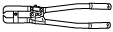
49 T025 001
Boot clamp crimpers
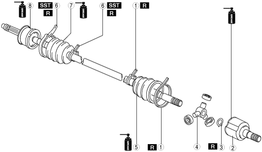
REAR DRIVE SHAFT DISASSEMBLY/ASSEMBLY
id031300800700
Special Service Tool (SST)
|
49 T025 001
Boot clamp crimpers
|
|
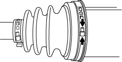
1. Disassemble in the order shown in the figure.
2. Assemble in the reverse order of removal.
atstjw00000059
|
|
1
|
Boot band (differential side)
|
|
2
|
Outer ring
(See Outer Ring Disassembly Note.)
(See Outer Ring Assembly Note.)
|
|
3
|
Snap ring
|
|
4
|
Tripod joint
|
|
5
|
Boot (differential side)
|
|
6
|
Boot band (wheel side)
|
|
7
|
Boot (wheel side)
|
|
8
|
Shaft and ball joint component
|
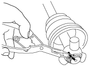
Boot Band (Differential Side) Disassembly Note
Type A
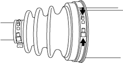
1. Grasp the boot band at the point shown in the figure using pliers, and remove the band.
ac9wzw00005701
|
Type B
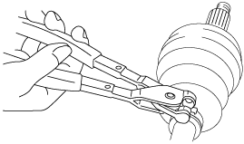
1. Remove the boot band using end clamp pliers.
aatjjw00009759
|
Outer Ring Disassembly Note
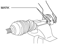
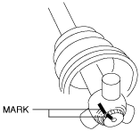
1. Place alignment marks on the shaft and outer ring.
azzzcw00000112
|
2. Remove the outer ring from the shaft.
3. Wipe off grease on the outer ring using a clean rag.
Snap Ring, Tripod Joint Disassembly Note
1. Place alignment marks on the shaft and tripod joint.
azzzcw00000113
|
2. Remove the snap ring using snap ring pliers.
atstjw00000054
|
3. Remove the tripod joint from the shaft.
4. Wipe off grease on the shaft and tripod joint using a clean rag.
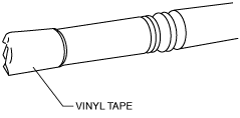
Boot (Differential Side) Disassembly Note
1. Wrap vinyl tape around the spline area of the shaft to prevent damage to the boot.
azzzcw00000114
|
2. Remove the boot (differential side).
3. Wipe off grease on the boot (differential side) using a clean rag.
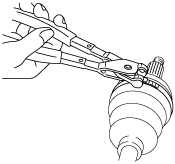
Boot Band (Wheel Side) Disassembly Note
1. Remove the boot band using end clamp pliers.
aatjjw00009768
|
Boot (Wheel Side) Disassembly Note
1. Wrap vinyl tape around the spline area of the shaft to prevent damage to the boot.
azzzcw00000114
|
2. Remove the boot (wheel side).
3. Wipe off grease on the boot (wheel side) and ball joint using a clean rag.
Boot (Wheel Side) Assembly Note
1. Insert the shaft through the boot (wheel side) with vinyl tape wrapped around the spline area of the shaft.
2. Apply the specified grease to the ball joint and boot (wheel side).
3. Assemble the boot (wheel side) to the ball joint.
Boot Band (Wheel Side) Assembly Note
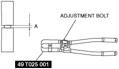
1. Adjust opening A of the SST to the standard by rotating the adjustment bolt.
azzzcw00000115
|
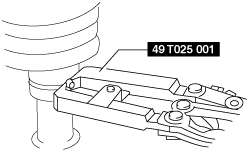
2. Crimp the boot band using the SST.
atstjw00000048
|
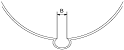
3. Verify that crimp B of the boot band is within the standard.
atstjw00000049
|
4. Verify that the boot band does not protrude from the boot band assembly area.
Boot (Differential Side) Assembly Note
1. Insert the shaft through the boot (differential side) with vinyl tape left wrapped around the spline area of the shaft.
2. Remove the vinyl tape left wrapped around the spline area of the shaft.
Tripod Joint, Snap Ring Assembly Note
1. Assemble the tripod joint with the alignment marks on the shaft and tripod joint aligned.
azzzcw00000113
|
2. Assemble a new snap ring using snap ring pliers.
atstjw00000054
|
3. Verify that the snap ring is assembled correctly in the groove of the shaft.
Outer Ring Assembly Note
1. Apply the specified grease to the outer ring and boot (differential side).
2. Align the shaft and outer ring with the alignment mark and assemble the outer ring.
azzzcw00000112
|
3. Assemble the boot (differential side) to the outer ring.
4. Set the drive shaft to the standard length.
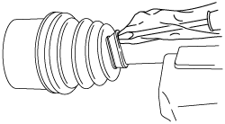
5. Release any trapped air from the boot by carefully lifting up the small end of the boot with a screwdriver wrapped in a clean rag.
aatjjw00009777
|
6. Verify that the drive shaft length is within the standard when the inside of the boot is at atmospheric pressure.
Boot Band (Differential Side) Assembly Note
Type A
1. Grasp the boot band at the point shown in the figure using pliers and tighten the boot band.
ac9wzw00005702
|
Type B
1. Adjust opening A of the SST to the standard by rotating the adjustment bolt.
azzzcw00000115
|
2. Crimp the boot band using the SST.
atstjw00000048
|
3. Verify that crimp B of the boot band is within the standard.
atstjw00000049
|
4. Verify that the boot band does not protrude from the boot band assembly area.