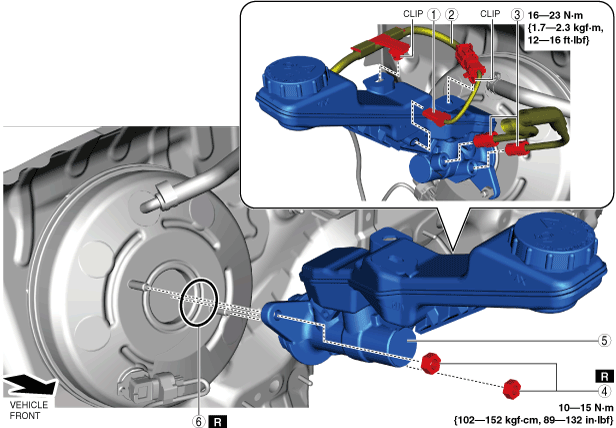
MASTER CYLINDER REMOVAL/INSTALLATION [R.H.D.]
id041100801352
Special Service Tool (SST)
|
49 JP01 003
Holder
|
 |
—
|
—
|
-
Caution
-
• When removing/installing the master cylinder, be careful not to spill brake fluid on the power brake unit vacuum sensor. Otherwise, brake fluid may get on the power brake unit vacuum sensor and damage it.
• Brake fluid will damage painted surfaces. Be careful not to spill any on painted surfaces. In addition, if there is any brake fluid on the wiring harness, the wire insulation may corrode causing a malfunction such as a short circuit. If brake fluid gets on a painted surface or wiring harness, wash and flush it off completely with water immediately.
-
Note
-
• Tighten the brake pipe flare nut using any commercially available flare nut wrench.
1. Disconnect the negative battery terminal. (See NEGATIVE BATTERY TERMINAL DISCONNECTION/CONNECTION.)
2. Remove in the order indicated in the table.
3. If the master cylinder is replaced as a single unit, adjust the power brake unit rod. (See Rod Adjustment Note.)
4. Install in the reverse order of removal.
5. After installation, add brake fluid, bleed the air, and inspect for fluid leakage. (See BRAKE FLUID AIR BLEEDING.)
|
1
|
Brake fluid level sensor connector
|
|
2
|
Brake fluid level sensor wiring harness
|
|
3
|
Brake pipe
|
|
4
|
Nut
|
|
5
|
Master cylinder
|
|
6
|
O-ring
|
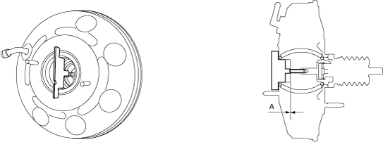
Rod Adjustment Note
1. Install the plate as shown in the figure and verify that the clearance between the rod end and the plate is within the standard.
-
Standard A
-
0 mm {0 in}
-
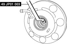
• If not within the standard, adjust the rod position using the following procedure.
- (1) Install the SST as shown in the figure.
-
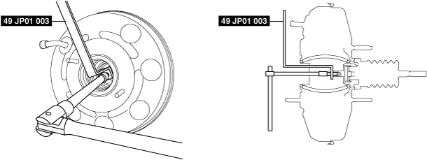
- (2) Rotate the socket wrench in either direction with the SST secured to adjust the rod position.
-
-
Note
-
• When the socket wrench is rotated clockwise as viewed from the front of the vehicle, the rod moves towards the rear of the vehicle.
• When the socket wrench is rotated counterclockwise as viewed from the front of the vehicle, the rod moves towards the front of the vehicle.
• The rod moves back and forth approx. 1 mm for each rotation.