REAR ABS WHEEL-SPEED SENSOR INSPECTION [4WD]
id0415008002a5
-
Caution
-
• Do not allow a magnetized tool such as a magnetized screwdriver to come into contact with the ABS sensor rotor. If the ABS sensor rotor becomes magnetized it will be unable to read the rear ABS wheel-speed sensor waveform correctly resulting in an ABS system malfunction to be determined and the inability to perform ABS control. If a magnetized object comes into contact with the ABS sensor rotor, it will be necessary to newly replace the rear drive shaft (ABS sensor rotor).
Sensor Output Value Inspection
-
Caution
-
• Resistance inspection using other testers may cause damage to the rear ABS wheel-speed sensor internal circuit. Be sure to use the M-MDS to inspect the rear ABS wheel-speed sensor.
1. Switch the ignition OFF.
2. Connect the M-MDS to the DLC-2.
3. Select the following PIDs using the M-MDS:
-
• WSPD_SEN_LR (LR ABS wheel-speed sensor)
• WSPD_SEN_RR (RR ABS wheel-speed sensor)
4. Start the engine and drive the vehicle.
5. Verify that the display of the M-MDS shows the same value as the speedometer.
-
Installation Visual Inspection
1. Inspect the following items:
-
• If there is any malfunction, replace the applicable part.
- (1) Excessive play of the rear ABS wheel-speed sensor
-
- (2) Deformation of the rear ABS wheel-speed sensor
-
- (3) Deformation or damage of the ABS sensor rotor
-
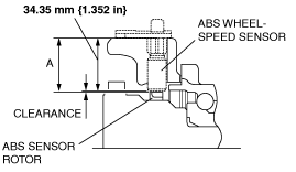
Clearance Inspection
1. Remove the rear ABS wheel-speed sensor. (See REAR ABS WHEEL-SPEED SENSOR REMOVAL/INSTALLATION [4WD].)
2. Measure the distance between the rear ABS wheel-speed sensor installation surface and the ABS sensor rotor. This is dimension A.
3. Calculate the clearance between the rear ABS wheel-speed sensor and the ABS sensor rotor using the following formula:
-
Clearance (mm {in}) = A-34.35 {1.352}
4. Verify that the clearance between the ABS sensor rotor and the rear ABS wheel-speed sensor is as indicated below.
-
-
Clearance
-
• 0.48—1.33 mm {0.019—0.052 in}