 |
ac9uuw00007544
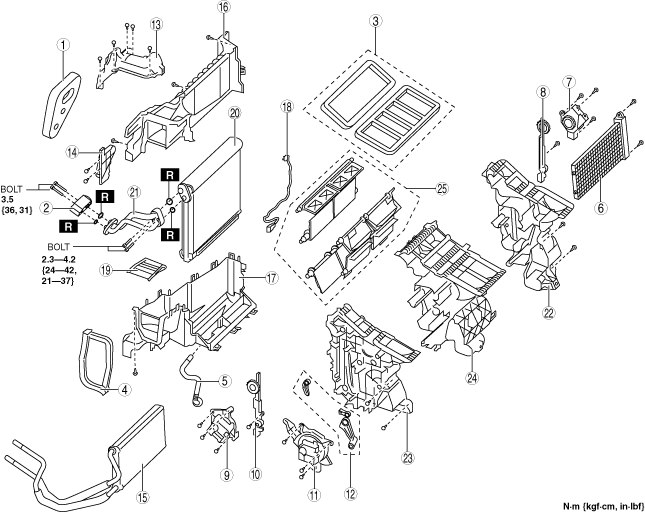
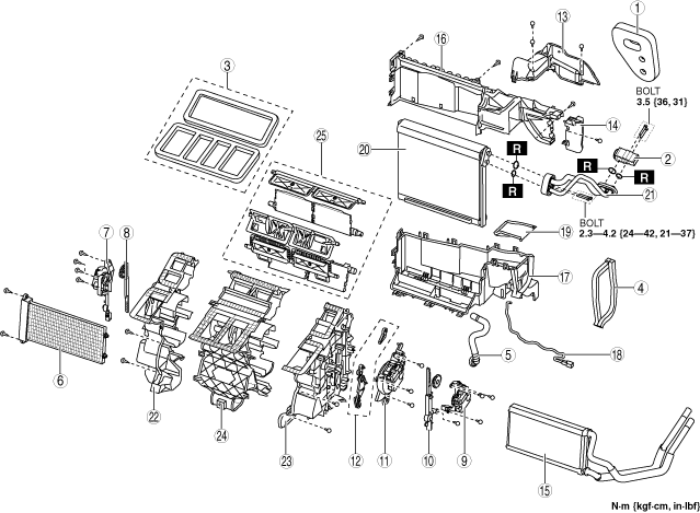
FRONT A/C UNIT DISASSEMBLY/ASSEMBLY
id071100802400
L.H.D.
1. Disassemble in the order indicated in the table.
ac9uuw00007544
|
|
Step |
Part name |
Disassembly/assembly of main parts |
||
|---|---|---|---|---|
|
Front heater core |
Evaporator temperature sensor |
Front evaporator |
||
|
1
|
Polyurethane foam
|
X
|
X
|
X
|
|
2
|
Front expansion valve
|
-
|
-
|
X
|
|
3
|
Adhesive polyurethane A
|
-
|
-
|
-
|
|
4
|
Adhesive polyurethane B
|
-
|
-
|
-
|
|
5
|
Drain hose
|
-
|
-
|
-
|
|
6
|
Cover
|
-
|
-
|
-
|
|
7
|
Driver-side front air mix actuator
|
-
|
X
|
X
|
|
8
|
Driver-side front air mix link (See Front air mix link assembly note.)
|
-
|
-
|
-
|
|
9
|
Passenger-side front air mix actuator
|
X
|
X
|
X
|
|
10
|
Passenger-side front air mix link (See Front air mix link assembly note.)
|
X
|
X
|
X
|
|
11
|
Front airflow mode actuator
|
-
|
-
|
-
|
|
12
|
Front airflow mode link set
|
-
|
-
|
-
|
|
13
|
Front A/C case A
|
X
|
X
|
X
|
|
14
|
Plate A
|
X
|
X
|
X
|
|
15
|
Front heater core
|
X
|
X
|
X
|
|
16
|
Front A/C case B
|
-
|
X
|
X
|
|
17
|
Front A/C case C
|
-
|
X
|
X
|
|
18
|
Evaporator temperature sensor
|
-
|
X
|
X
|
|
19
|
Plate B
|
-
|
-
|
-
|
|
20
|
Front evaporator
|
-
|
-
|
X
|
|
21
|
Front evaporator pipe
|
-
|
-
|
X
|
|
22
|
Front A/C case D
|
-
|
-
|
-
|
|
23
|
Front A/C case E
|
-
|
-
|
-
|
|
24
|
Front A/C case F
|
-
|
-
|
-
|
|
25
|
Door damper
|
-
|
-
|
-
|
2. Assemble in the reverse order of disassembly.
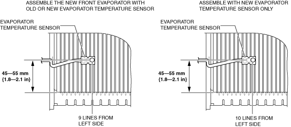
Evaporator temperature sensor assembly note
1. Assemble the evaporator temperature sensor as shown in the figure.
ac9wzw00003611
|
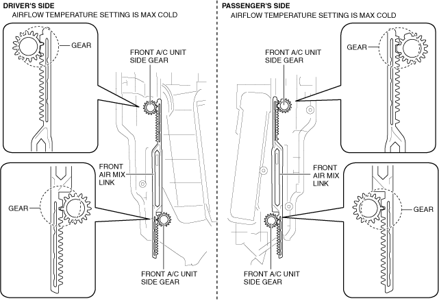
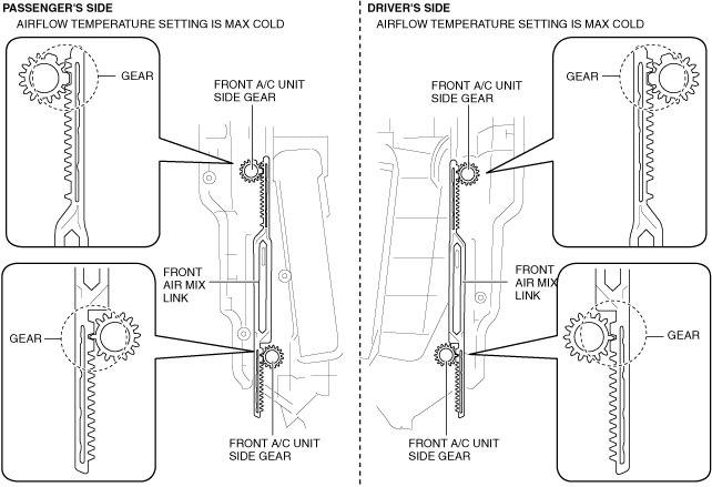
Front air mix link assembly note
1. Align the positions of the front A/C unit side gears with the positions of the front air mix link gears as shown in the figure.
ac9wzw00003612
|
R.H.D.
1. Disassemble in the order indicated in the table.
ac9wzw00003613
|
|
Step |
Part name |
Disassembly/assembly of main parts |
||
|---|---|---|---|---|
|
Front heater core |
Evaporator temperature sensor |
Front evaporator |
||
|
1
|
Polyurethane foam
|
X
|
X
|
X
|
|
2
|
Front expansion valve
|
-
|
-
|
X
|
|
3
|
Adhesive polyurethane A
|
-
|
-
|
-
|
|
4
|
Adhesive polyurethane B
|
-
|
-
|
-
|
|
5
|
Drain hose
|
-
|
-
|
-
|
|
6
|
Cover
|
-
|
-
|
-
|
|
7
|
Driver-side front air mix actuator
|
-
|
X
|
X
|
|
8
|
Driver-side front air mix link (See Front air mix link assembly note.)
|
-
|
-
|
-
|
|
9
|
Passenger-side front air mix actuator
|
X
|
X
|
X
|
|
10
|
Passenger-side front air mix link (See Front air mix link assembly note.)
|
X
|
X
|
X
|
|
11
|
Front airflow mode actuator
|
-
|
-
|
-
|
|
12
|
Front airflow mode link set
|
-
|
-
|
-
|
|
13
|
Front A/C case A
|
X
|
X
|
X
|
|
14
|
Plate A
|
X
|
X
|
X
|
|
15
|
Front heater core
|
X
|
X
|
X
|
|
16
|
Front A/C case B
|
-
|
X
|
X
|
|
17
|
Front A/C case C
|
-
|
X
|
X
|
|
18
|
Evaporator temperature sensor
|
-
|
X
|
X
|
|
19
|
Plate B
|
-
|
-
|
-
|
|
20
|
Front evaporator
|
-
|
-
|
X
|
|
21
|
Front evaporator pipe
|
-
|
-
|
X
|
|
22
|
Front A/C case D
|
-
|
-
|
-
|
|
23
|
Front A/C case E
|
-
|
-
|
-
|
|
24
|
Front A/C case F
|
-
|
-
|
-
|
|
25
|
Door damper
|
-
|
-
|
-
|
2. Assemble in the reverse order of disassembly.
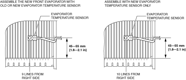
Evaporator temperature sensor assembly note
1. Assemble the evaporator temperature sensor as shown in the figure.
ac9wzw00003614
|
Front air mix link assembly note
1. Align the positions of the front A/C unit side gears with the positions of the front air mix link gears as shown in the figure.
ac9wzw00003615
|