DTC B10C9:1F [START STOP UNIT]


id0902p6026300


With Keyless Entry System

Description

Keyless antenna (interior, center) circuit malfunction

Detection condition
•  Start stop unit detects an open circuit or short to ground in the keyless antenna (interior, center) with the ignition switched off.
Fail-safe
Not applicable
Possible cause
•  Keyless antenna (interior, center) connector or terminal malfunction
•  Start stop unit connector or terminal malfunction
•  Short to ground in wiring harness between the following terminals:
?  Start stop unit terminal 2I—Keyless antenna (interior, center) terminal B
?  Start stop unit terminal 2K—Keyless antenna (interior, center) terminal A
•  Open circuit in wiring harness between the following terminals:
?  Start stop unit terminal 2I—Keyless antenna (interior, center) terminal B
?  Start stop unit terminal 2K—Keyless antenna (interior, center) terminal A
•  Keyless antenna (interior, center) malfunction
•  Start stop unit malfunction

Diagnostic Procedure

Step

Inspection

Action

1
INSPECT KEYLESS ANTENNA (INTERIOR, CENTER) CONNECTOR CONDITION
•  Switch the ignition off.
•  Disconnect the negative battery terminal.
•  Disconnect the keyless antenna (interior, center) connector.
•  Inspect the connector engagement and connection condition and inspect the terminals for damage, deformation, corrosion, or disconnection.
•  Is the connector normal?
Yes
Go to the next step.
No
Repair or replace the connector, then go to Step 6.
2
INSPECT START STOP UNIT CONNECTOR CONDITION
•  Disconnect the start stop unit connector.
•  Inspect the connector engagement and connection condition and inspect the terminals for damage, deformation, corrosion, or disconnection.
•  Is the connector normal?
Yes
Go to the next step.
No
Repair or replace the connector, then go to Step 6.
3
INSPECT KEYLESS ANTENNA (INTERIOR, CENTER) CIRCUIT FOR SHORT TO GROUND
•  Verify that the start stop unit and keyless antenna (interior, center) connectors are disconnected.
•  Inspect for continuity between the following terminals (wiring harness-side) and body ground:
?  Keyless antenna (interior, center) terminal B
?  Keyless antenna (interior, center) terminal A
•  Is there continuity?
Yes
Refer to the wiring diagram and verify whether or not there is a common connector between the following terminals:
•  Start stop unit terminal 2I—Keyless antenna (interior, center) terminal B
•  Start stop unit terminal 2K—Keyless antenna (interior, center) terminal A
If there is a common connector:
•  Determine the malfunctioning part by inspecting the common connector and the terminal for corrosion, damage, or pin disconnection, and the common wiring harness for a short to ground.
•  Repair or replace the malfunctioning part.
If there is no common connector:
•  Repair or replace the wiring harness which has a short to ground.
Go to Step 6.
No
Go to the next step.
4
INSPECT KEYLESS ANTENNA (INTERIOR, CENTER) CIRCUIT FOR OPEN CIRCUIT
•  Verify that the start stop unit and keyless antenna (interior, center) connectors are disconnected.
•  Inspect for continuity between the following terminals (wiring harness-side):
?  Start stop unit terminal 2I—Keyless antenna (interior, center) terminal B
?  Start stop unit terminal 2K—Keyless antenna (interior, center) terminal A
•  Is there continuity?
Yes
Go to the next step.
No
Refer to the wiring diagram and verify whether or not there is a common connector between the following terminals:
•  Start stop unit terminal 2I—Keyless antenna (interior, center) terminal B
•  Start stop unit terminal 2K—Keyless antenna (interior, center) terminal A
If there is a common connector:
•  Determine the malfunctioning part by inspecting the common connector and the terminal for corrosion, damage, or pin disconnection, and the common wiring harness for an open circuit.
•  Repair or replace the malfunctioning part.
If there is no common connector:
•  Repair or replace the wiring harness which has an open circuit.
Go to Step 6.
5
VERIFY IF MALFUNCTIONING LOCATION IS KEYLESS ANTENNA (INTERIOR, CENTER) DEPENDING ON REPEATABILITY
•  Always reconnect all disconnected connectors.
•  Connect the negative battery terminal.
•  Clear the DTC for the start stop unit using the M-MDS.
•  Perform the following work:
?  Switch the ignition off.
?  Open the front door (driver's side).
?  Close all the doors and liftgate.
•  Retrieve the start stop unit DTCs using the M-MDS.
•  Is the same DTC displayed?
Yes
Replace the keyless antenna (interior, center), then go to the next step.
No
Go to Step 7.
6
VERIFY THAT REPAIRS HAVE BEEN COMPLETED
•  Always reconnect all disconnected connectors.
•  Connect the negative battery terminal.
•  Clear the DTC for the start stop unit using the M-MDS.
•  Perform the following work:
?  Switch the ignition off.
?  Open the front door (driver's side).
?  Close all the doors and liftgate.
•  Retrieve the start stop unit DTCs using the M-MDS.
•  Is the same DTC displayed?
Yes
Repeat the inspection from Step 1.
•  If the malfunction recurs, replace the start stop unit.
Go to the next step.
No
Go to the next step.
7
VERIFY IF OTHER DTCs DISPLAYED
•  Are any other DTCs displayed?
Yes
Repair or replace the malfunctioning part according to the applicable DTC troubleshooting.
No
DTC troubleshooting completed.


With Advanced Keyless Entry System

Description

Keyless antenna (interior, front) circuit malfunction

Detection condition
•  Start stop unit detects an open circuit or short to ground in the keyless antenna (interior, front) circuit with the ignition switched off.
Fail-safe
•  Inhibits the door lock/unlock control using the advanced keyless entry system.
Possible cause
•  Keyless antenna (interior, front) connector or terminal malfunction
•  LF control unit connector or terminal malfunction
•  Short to ground in wiring harness between the following terminals:
?  LF control unit terminal K—Keyless antenna (interior, front) terminal B
?  LF control unit terminal M—Keyless antenna (interior, front) terminal A
•  Open circuit in wiring harness between the following terminals:
?  LF control unit terminal K—Keyless antenna (interior, front) terminal B
?  LF control unit terminal M—Keyless antenna (interior, front) terminal A
•  LF control unit malfunction
•  Keyless antenna (interior, front) malfunction
•  Start stop unit malfunction

Diagnostic Procedure

Step

Inspection

Action

1
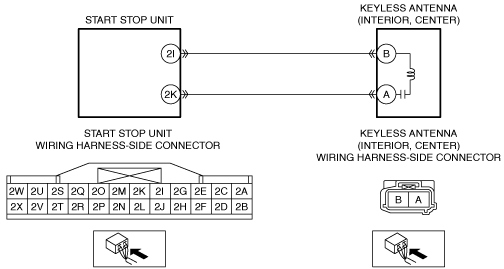
INSPECT KEYLESS ANTENNA (INTERIOR, FRONT) CONNECTOR CONDITION
•  Switch the ignition off.
•  Disconnect the negative battery terminal.
•  Disconnect the keyless antenna (interior, front) connector.
•  Inspect the connector engagement and connection condition and inspect the terminals for damage, deformation, corrosion, or disconnection.
•  Is the connector normal?
Yes
Go to the next step.
No
Repair or replace the connector, then go to Step 7.
2
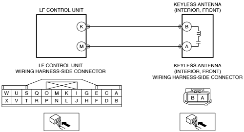
INSPECT LF CONTROL UNIT CONNECTOR CONDITION
•  Disconnect the LF control unit connector.
•  Inspect the connector engagement and connection condition and inspect the terminals for damage, deformation, corrosion, or disconnection.
•  Is the connector normal?
Yes
Go to the next step.
No
Repair or replace the connector, then go to Step 7.
3
INSPECT KEYLESS ANTENNA (INTERIOR, FRONT) CIRCUIT FOR SHORT TO GROUND
•  Verify that the LF control unit and keyless antenna (interior, front) connectors are disconnected.
•  Inspect for continuity between the following terminals (wiring harness-side) and body ground:
?  Keyless antenna (interior, front) terminal B
?  Keyless antenna (interior, front) terminal A
•  Is there continuity?
Yes
Refer to the wiring diagram and verify whether or not there is a common connector between the following terminals:
•  LF control unit terminal K—Keyless antenna (interior, front) terminal B
•  LF control unit terminal M—Keyless antenna (interior, front) terminal A
If there is a common connector:
•  Determine the malfunctioning part by inspecting the common connector and the terminal for corrosion, damage, or pin disconnection, and the common wiring harness for a short to ground.
•  Repair or replace the malfunctioning part.
If there is no common connector:
•  Repair or replace the wiring harness which has a short to ground.
Go to Step 7.
No
Go to the next step.
4
INSPECT KEYLESS ANTENNA (INTERIOR, FRONT) CIRCUIT FOR OPEN CIRCUIT
•  Verify that the LF control unit and keyless antenna (interior, front) connectors are disconnected.
•  Inspect for continuity between the following terminals (wiring harness-side):
?  LF control unit terminal K—Keyless antenna (interior, front) terminal B
?  LF control unit terminal M—Keyless antenna (interior, front) terminal A
•  Is there continuity?
Yes
Go to the next step.
No
Refer to the wiring diagram and verify whether or not there is a common connector between the following terminals:
•  LF control unit terminal K—Keyless antenna (interior, front) terminal B
•  LF control unit terminal M—Keyless antenna (interior, front) terminal A
If there is a common connector:
•  Determine the malfunctioning part by inspecting the common connector and the terminal for corrosion, damage, or pin disconnection, and the common wiring harness for an open circuit.
•  Repair or replace the malfunctioning part.
If there is no common connector:
•  Repair or replace the wiring harness which has an open circuit.
Go to Step 7.
5
INSPECT LF CONTROL UNIT
•  Inspect the LF control unit.
•  Is the LF control unit normal?
Yes
Go to the next step.
No
Replace the LF control unit, then go to Step 7.
6
VERIFY IF MALFUNCTIONING LOCATION IS KEYLESS ANTENNA (INTERIOR, FRONT) DEPENDING ON REPEATABILITY
•  Always reconnect all disconnected connectors.
•  Connect the negative battery terminal.
•  Clear the DTC for the start stop unit using the M-MDS.
•  Perform the following work:
?  Switch the ignition off.
?  Open the front door (driver's side).
?  Close all the doors and liftgate.
•  Retrieve the start stop unit DTCs using the M-MDS.
•  Is the same DTC displayed?
Yes
Replace the keyless antenna (interior, front), then go to the next step.
No
Go to Step 8.
7
VERIFY THAT REPAIRS HAVE BEEN COMPLETED
•  Always reconnect all disconnected connectors.
•  Connect the negative battery terminal.
•  Clear the DTC for the start stop unit using the M-MDS.
•  Perform the following work:
?  Switch the ignition off.
?  Open the front door (driver's side).
?  Close all the doors and liftgate.
•  Retrieve the start stop unit DTCs using the M-MDS.
•  Is the same DTC displayed?
Yes
Repeat the inspection from Step 1.
•  If the malfunction recurs, replace the start stop unit.
Go to the next step.
No
Go to the next step.
8
VERIFY IF OTHER DTCs DISPLAYED
•  Are any other DTCs displayed?
Yes
Repair or replace the malfunctioning part according to the applicable DTC troubleshooting.
No
DTC troubleshooting completed.