|
1
|
POWER WINDOW MAIN SWITCH CONNECTOR INSPECTION
• Switch the ignition off.
• Disconnect the negative battery terminal.
• Disconnect the power window main switch connector.
• Inspect the connector engagement and connection condition and inspect the terminals for damage, deformation, corrosion, or disconnection.
• Is the connector normal?
|
Yes
|
Go to the next step.
|
|
No
|
Repair or replace the connector, then go to Step 7.
|
|
2
|
POWER WINDOW MOTOR CONNECTOR INSPECTION
• Disconnect the power window motor connector.
• Inspect the connector engagement and connection condition and inspect the terminals for damage, deformation, corrosion, or disconnection.
• Is the connector normal?
|
Yes
|
Go to the next step.
|
|
No
|
Repair or replace the connector, then go to Step 7.
|
|
3
|
VERIFY IF MALFUNCTION CAUSE IS POWER WINDOW MAIN SWITCH POWER SUPPLY CIRCUIT
• Reconnect all the disconnected connectors.
• Connect the negative battery terminal.
• Measure the voltage at the following terminals (vehicle wiring harness side).
-
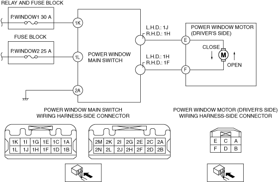
? Power window main switch terminal 1K
? Power window main switch terminal 1L
• Is the voltage B+?
|
Yes
|
Go to the next step.
|
|
No
|
Inspect the P.WINDOW1 30A fuse and P.WINDOW2 25A fuse.
• If any fuse is damaged:
-
? Replace the fuse.
• If the fuses are normal:
Refer to the wiring diagram and verify if there is a common connector between the following terminals.
-
? P.WINDOW1 30A fuse and power window main switch terminal 1K
? P.WINDOW2 25A fuse and power window main switch terminal 1L
If there is a common connector:
-
• Inspect the common connector and terminals for corrosion, damage, or disconnection and the common wiring harnesses for an open circuit to determine the malfunctioning location.
• Repair or replace the malfunctioning location.
If there is no common connector:
-
• Repair or replace the wiring harness which has an open circuit.
Go to Step 7.
|
|
4
|
VERIFY IF MALFUNCTION CAUSE IS OPEN CIRCUIT IN WIRING HARNESS BETWEEN POWER WINDOW MAIN SWITCH AND BODY GROUND
• Disconnect the negative battery terminal.
• Disconnect the power window main switch connector.
• Inspect for continuity between power window main switch terminal 2A (vehicle wiring harness side) and body ground.
• Is there continuity?
|
Yes
|
Go to the next step.
|
|
No
|
Refer to the wiring diagram and verify if there is a common connector between power window main switch terminal 2A and body ground.
If there is a common connector:
• Inspect the common connector and terminals for corrosion, damage, or disconnection and the common wiring harnesses for an open circuit to determine the malfunctioning location.
• Repair or replace the malfunctioning location.
If there is no common connector:
• Repair or replace the wiring harness which is an open circuit.
Go to Step 7.
|
|
5
|
POWER WINDOW MOTOR TERMINALS E AND F INSPECTION
• Reconnect all the disconnected connectors.
• Connect the negative battery terminal.
• Measure the voltage at power window motor terminals E and F while operating the power window main switch.
-
? Terminal E during close operation
? Terminal F during open operation
• Is the voltage B+?
|
Yes
|
Replace the power window motor, then go to Step 7.
|
|
No
|
Go to the next step.
|
|
6
|
POWER WINDOW MAIN SWITCH TERMINALS 1J AND 1H INSPECTION
• Measure the voltage at power window main switch terminals 1J and 1H.
• Is the power window main switch voltage normal?
|
Yes
|
Refer to the wiring diagram and verify if there is a common connector between the following terminals.
• Power window main switch terminal 1J (L.H.D.)/1H (R.H.D.) and power window motor terminal E
• Power window main switch terminal 1H (L.H.D.)/1F (R.H.D.) and power window motor terminal F
If there is a common connector:
• Inspect the common connector and terminals for corrosion, damage, or disconnection and the common wiring harnesses for an open or short circuit to determine the malfunctioning location.
• Repair or replace the malfunctioning location.
If there is no common connector:
• Repair or replace the wiring harness which has an open or short circuit.
Go to the next step.
|
|
No
|
Replace the power window main switch, then go to the next step.
|
|
7
|
VERIFY IF MALFUNCTION CAUSE IS CORRECTED
• Does the power window system operate normally?
|
Yes
|
Troubleshooting completed. (Explain the problem to the customer.)
|
|
No
|
Verify the malfunction symptom in the symptom troubleshooting chart and perform the other applicable malfunction diagnosis.
|