 |
ac9wzw00004955
POWER OUTER MIRROR INSPECTION
id091200002700
Mirror Glass Inspection
1. Disconnect the negative battery terminal. (See NEGATIVE BATTERY TERMINAL DISCONNECTION/CONNECTION.)
2. Remove the front door trim. (See FRONT DOOR TRIM REMOVAL/INSTALLATION.)
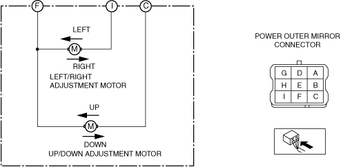
3. Apply battery positive voltage and connect the ground to the power outer mirror terminals and inspect the power outer mirror operation.
ac9wzw00004955
|
|
Mirror operation direction |
Battery positive voltage connect terminal |
Ground connect terminal |
|---|---|---|
|
Up
|
C
|
F
|
|
Down
|
F
|
C
|
|
Left
|
I
|
F
|
|
Right
|
F
|
I
|
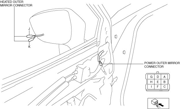
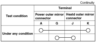
Heated Outer Mirror Inspection
1. Disconnect the negative battery terminal. (See NEGATIVE BATTERY TERMINAL DISCONNECTION/CONNECTION.)
2. Remove the following parts:
3. Verify that the continuity between heated outer mirror connector terminals is as indicated in the table.
ac9uuw00009402
|
ac5uuw00003737
|
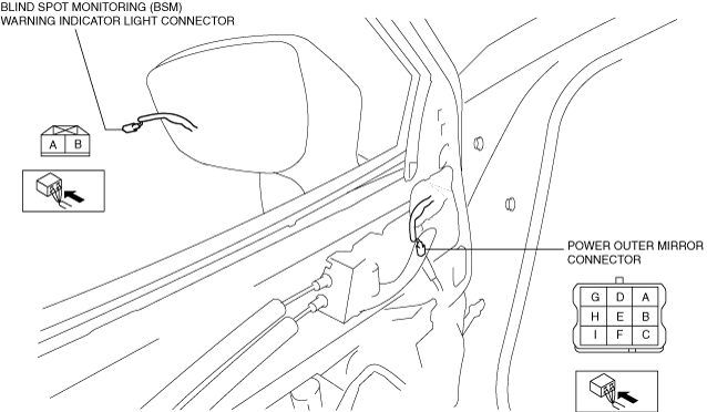
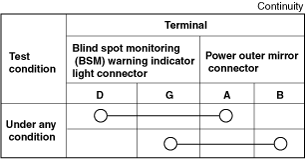
Blind Spot Monitoring (BSM) Warning Indicator Light Inspection
1. Disconnect the negative battery terminal. (See NEGATIVE BATTERY TERMINAL DISCONNECTION/CONNECTION.)
2. Remove the following parts:
3. Verify that the continuity between blind spot monitoring (BSM) warning indicator light connector terminals is as indicated in the table.
ac9uuw00009403
|
ac9uuw00009404
|