 |
am2zzw00008324
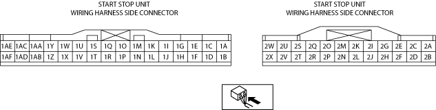
START STOP UNIT INSPECTION
id091400110400
1. Remove the Column cover. (See COLUMN COVER REMOVAL/INSTALLATION.)
2. Verify that the voltages of each of the terminals are as indicated in the terminal voltage table (reference).
Terminal Voltage Table (Reference)
am2zzw00008324
|
|
Terminal |
Signal name |
Connected to |
Measurement conditions |
Voltage (V) |
Inspection item(s) |
|||
|---|---|---|---|---|---|---|---|---|
|
1A
|
Power supply
|
INTERIOR 10 A fuse
|
Under any condition
|
B+
|
• INTERIOR 10 A fuse
• Battery
|
|||
|
1B
|
Power supply
|
C/U IG1 15 A fuse
|
Ignition switched ON (engine off)
|
B+
|
• C/U IG1 15 A fuse
• Battery
|
|||
|
Ignition switched OFF (LOCK) or at ACC
|
1.0 or less
|
|||||||
|
1C
|
Brake switch
|
Brake switch
|
Brake pedal depressed
|
B+
|
Brake switch
|
|||
|
Brake pedal not depressed
|
1.0 or less
|
|||||||
|
1D
|
Starter monitor
|
Starter relay
|
Ignition switched ON (engine off)
|
Other than selector lever is in P or N position
|
B+
|
• Start Stop Unit
• Starter relay
• PCM
|
||
|
Selector lever is in P or N position
|
1.0 or less
|
|||||||
|
1E
|
ACC monitor
|
MIRROR 7.5 A fuse
|
Switch the ignition to ACC or ON (engine off or on)
|
B+
|
• MIRROR 7.5 A fuse
• ACC relay
• Battery
|
|||
|
Ignition switched OFF (LOCK)
|
1.0 or less
|
|||||||
|
1F
|
Selector lever position switch (ATX)
|
TCM
|
Other than selector lever is in P or N position
|
B+
|
TCM
|
|||
|
Selector lever is in P or N position
|
1.0 or less
|
|||||||
|
1G
|
Hazard warning switch signal
|
Hazard warning switch
|
Hazard warning switch not pressed (OFF)
|
B+
|
Hazard warning switch
|
|||
|
Hazard warning switch pressed (ON)
|
1.0 or less
|
|||||||
|
1H
|
Push button start 1
|
Push button start
|
Push button start pressed
|
1.0 or less
|
Push button start
|
|||
|
Push button start not pressed
|
B+
|
|||||||
|
1I
|
Push button illumination
|
Push button start
|
Determination using terminal voltage inspection is not possible.
|
Push button start
|
||||
|
1J
|
P position
|
Not P position switch
|
Selector lever is in P position
|
B+
|
Not P position switch
|
|||
|
Except above
|
1.0 or less
|
|||||||
|
1K
|
Push button illumination (green)
|
Push button start
|
Engine starting conditions are met
|
1.0 or less
|
Push button start
|
|||
|
Except above
|
B+
|
|||||||
|
1M
|
Push button illumination (amber)
|
Push button start
|
Ignition switched to ACC or ON (engine off)
|
1.0 or less
|
Push button start
|
|||
|
Except above
|
B+
|
|||||||
|
1P
|
Lock input
|
• Door lock-link switch (driver's door)
• Power liftgate (PLG) control module*5
|
Driver's door locked
|
1.0 or less
|
• Door lock-link switch (driver's door)
• Power liftgate (PLG) control module*5
|
|||
|
Driver's door unlocked
|
B+*5
5.0*6
|
|||||||
|
1Q
|
Rear body control module (RBCM) communication
|
Rear body control module (RBCM)
|
Because this terminal is for communication, determination using terminal voltage inspection is not possible.
|
|||||
|
1S*3
|
Steering angle sensor power supply
|
Steering angle sensor
|
The specified time has elapsed since key placed outside vehicle and all doors locked
|
1.0 or less
|
Steering angle sensor
|
|||
|
Except above
|
Approx. 5
|
|||||||
|
1T*3
|
Steering angle sensor ground
|
Steering angle sensor
|
Under any condition
|
1.0 or less
|
Steering angle sensor
|
|||
|
1U*3
|
Steering angle sensor (signal A/D1)
|
Steering angle sensor
|
Steering wheel is turned to left and right
|
4.00—4.75Û0.25—0.75
|
Steering angle sensor
|
|||
|
1V
|
Windshield wiper switch signal (LO)
|
Front body control module (FBCM)
|
Ignition switch ON (engine off or on)
|
Other than windshield wiper switch at LO and HI
|
B+
|
Front body control module (FBCM)
|
||
|
Windshield wiper switch at LO
|
1.0 or less
|
|||||||
|
1W*3
|
Steering angle sensor (signal A/D1)
|
Steering angle sensor
|
Steering wheel is turned to left and right
|
4.00—4.75Û0.25—0.75
|
Steering angle sensor
|
|||
|
1X
|
Headlight switch signal (LO)
|
Front body control module (FBCM)
|
Light switch at position other than HEAD and passing
|
B+
|
Front body control module (FBCM)
|
|||
|
Light switch at HEAD position
|
1.0 or less
|
|||||||
|
1Y
|
Cruise control switch signal
|
Cruise control switch
|
OFF / CANCEL switch is pressed
|
0
|
Cruise control switch
|
|||
|
SET (-) switch is pressed
|
0.3
|
|||||||
|
SET (+) / RES (+) switch is pressed
|
0.6
|
|||||||
|
ON or MODE switch is pressed
|
1.1
|
|||||||
|
RES switch is pressed
|
1.5
|
|||||||
|
DISTANCE (+) switch is pressed
|
1.9
|
|||||||
|
DISTANCE (-) switch is pressed
|
2.4
|
|||||||
|
Except above
|
3.7
|
|||||||
|
1Z
|
Cruise control switch ground
|
Cruise control switch
|
Under any condition
|
1.0 or less
|
Cruise control switch
|
|||
|
1AA
|
Steering switch signal
|
Steering switch
|
INFO button is pressed
|
Approx. 2.3
|
Steering switch
|
|||
|
Except above
|
Approx. 3.4
|
|||||||
|
1AB
|
Steering switch ground
|
Steering switch
|
Under any condition
|
1.0 or less
|
Steering switch
|
|||
|
1AC
|
PATS+
|
Coil antenna (push button start)
|
Because this terminal is for communication, determination using terminal voltage inspection is not possible.
|
|||||
|
1AE
|
PATS-
|
Coil antenna (push button start)
|
Because this terminal is for communication, determination using terminal voltage inspection is not possible.
|
|||||
|
1AF
|
GROUND
|
Body ground
|
Under any condition
|
1.0 or less
|
Body ground
|
|||
|
2A
|
GROUND
|
Body ground
|
Under any condition
|
1.0 or less
|
Body ground
|
|||
|
2B
|
GROUND
|
Body ground
|
Under any condition
|
1.0 or less
|
Body ground
|
|||
|
2C
|
ACC relay control
|
ACC relay
|
Switch the ignition to ACC or ON (engine off or on)
|
B+
|
• ACC relay
• OUTLET relay
|
|||
|
Ignition switched OFF (LOCK)
|
1.0 or less
|
|||||||
|
2D
|
IG2 relay control
|
Front body control module (FBCM)
|
Ignition switched ON (engine off)
|
B+
|
Front body control module (FBCM)
|
|||
|
Ignition switched OFF (LOCK) or at ACC
|
1.0 or less
|
|||||||
|
2E
|
—
|
—
|
—
|
—
|
—
|
|||
|
2F*1
|
LF control unit communication
|
LF control unit
|
Because this terminal is for communication, determination using terminal voltage inspection is not possible.
|
|||||
|
2G
|
Shift lock
|
Shift lock solenoid
|
Ignition switch ON (engine off or on)
|
Selector lever at position except P
|
B+
|
Shift lock solenoid
|
||
|
Selector lever at P position and brake pedal depressed
|
1.0 or less
|
|||||||
|
2H*1
|
LF control unit communication
|
LF control unit
|
Because this terminal is for communication, determination using terminal voltage inspection is not possible.
|
|||||
|
2I*2
|
Keyless antenna (inside vehicle, center)
|
Keyless antenna (inside vehicle, center)
|
Because this terminal is for communication, determination using terminal voltage inspection is not possible.
|
|||||
|
2J
|
Push button start 2
|
Push button start
|
Push button start pressed
|
1.0 or less
|
Push button start
|
|||
|
Push button start not pressed
|
B+
|
|||||||
|
2K*2
|
Keyless antenna (inside vehicle, center)
|
Keyless antenna (inside vehicle, center)
|
Because this terminal is for communication, determination using terminal voltage inspection is not possible.
|
|||||
|
2L*2
|
Shield ground
|
Shield wire
|
Under any condition
|
1.0 or less
|
Body ground
|
|||
|
2M
|
HS-CAN+
|
—
|
Because this terminal is for communication, determination using terminal voltage inspection is not possible.
|
|||||
|
2O
|
HS-CAN-
|
—
|
Because this terminal is for communication, determination using terminal voltage inspection is not possible.
|
|||||
|
2Q
|
Keyless receiver power supply
|
Keyless receiver
|
Under any condition
|
Approx. 5
|
Keyless receiver
|
|||
|
2R
|
Keyless receiver communication
|
Keyless receiver
|
Because this terminal is for communication, determination using terminal voltage inspection is not possible.
|
|||||
|
2S
|
IG1 relay control
|
IG1 relay
|
Ignition switched ON (engine off)
|
B+
|
IG1 relay
|
|||
|
Ignition switched OFF (LOCK) or at ACC
|
1.0 or less
|
|||||||
|
2V
|
Starter relay
|
Starter relay
|
When cranking
|
B+
|
• Starter relay
• PCM
• Start stop unit
|
|||
|
Except above*6
|
1.0 or less, or B+*6
|
|||||||
|
2W
|
Power supply
|
AT 15 A fuse
|
Under any condition
|
B+
|
• AT 15 A fuse
• Battery
|
|||
|
2X
|
Power supply (ESCL)
|
SRS2/ESCL 15 A fuse
|
Under any condition
|
B+
|
• SRS2/ESCL 15 A fuse
• Battery
|
|||