PARKING ASSIST SYSTEM INITIALIZATION (CALIBRATION)
id092000841100
• Launch the initialization mode for the park assist system initialization.
-
? Rear mount camera removal/installation
? Liftgate removal/installation or adjustment
? Rear finisher removal/installation
? Part replacement having large effect on vehicle height such as tires, suspension, and wheels
Initialization
1. Empty the vehicle by having all occupants leave the vehicle and remove all the cargo except for the spare tire, jack and tools equipped on the vehicle.
-
Caution
-
• If the initialization is performed with the vehicle heavily loaded and the vehicle posture largely changed, the camera optical axis may not set to the correct position. Perform the initialization after unloading cargo and emptying the vehicle.
2. Adjust the wheel alignment, tire pressure. (See WHEEL AND TIRE SPECIFICATION.)
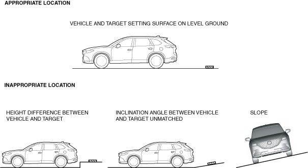
3. Move the vehicle to level ground.
-
Caution
-
• If the height and angle of the set surface is different between the vehicle and the target bar, the initialization cannot be performed correctly. Perform the initialization at a place where the vehicle and target bar can be set on a level ground.
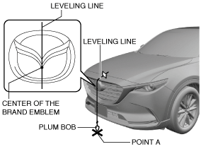
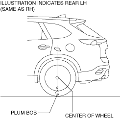
4. Adjust the SST (plum-bob) so that it is aligned with the center of the brand emblem, determine the center position at the front of the vehicle, and mark the center position (point A) on the floor surface.
-
Note
-
• The center of the brand emblem indicates the center position of the vehicle.
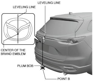
5. Adjust the SST (plum-bob) so that it is aligned with the center of the brand emblem, determine the center position at the rear of the vehicle, and mark the center position (point B) on the floor surface.
-
Note
-
• The center of the brand emblem indicates the center position of the vehicle.
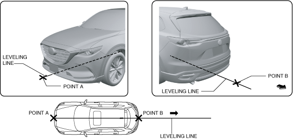
6. Secure the end of the leveling line over point A.
-
Note
-
• Use a commercially-available leveling line.
7. Pull the unsecured end of the leveling line to the vehicle rear so that it passes over point B.
8. Adjust the SST (plum bob) so that it crosses the center of the rear wheel and identify the center position of the wheel house.
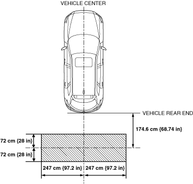
9. Verify that there is no color or object which prevents the detection of the target bar in the shaded area shown in the figure.
-
Caution
-
• If there is a color or an object which prevents the detection of the target bar in the shaded area shown in the figure, it could cause a poor adjustment or the precision may worsen. Under the following cases, move the vehicle or paint the shaded area shown in the figure so that the camera does not pick up a color or an object which could prevent the detection of the target bar.
-
? There is a color similar to target bar within shaded area shown in figure
? There is an object which reflects light strongly within shaded area shown in figure
? Light or linear shaped object is picked up within shaded area shown in figure
? Ceiling light reflects off floor and is picked up by camera
10. Print out 32 sheets of the following target paper without using scaling.
-
Note
-
• If the target paper cannot be printed, follow the dimensions shown in Step 13 to make target sheets.
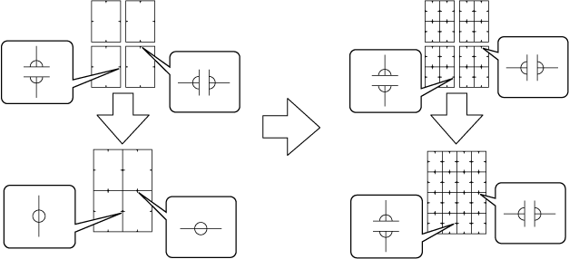
11. Cut the target papers along the line.
12. Align the center marks as shown in the figure, and tape them together using adhesive tape on the back side to make 2 adjustment target bars.
-
Caution
-
• When taping the target papers together, if adhesive tape is affixed to the front side of the target papers, light may reflect off the tape and it may cause a poor adjustment or the precision may worsen. Affix adhesive tape to the back side of the target papers when taping them together.
-
Note
-
• Tape 16 target papers together to make an adjustment target bar, and make 2 adjustment target bars.
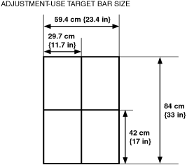
13. Verify that the dimensions of the taped target papers are as indicated in the figure.
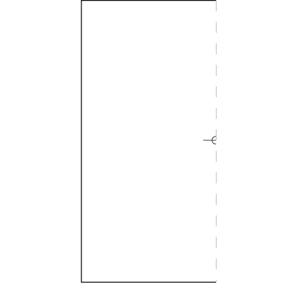
14. Print out 2 sheets of the following target paper A without using scaling.
-
Note
-
• If the target paper cannot be printed, follow the dimensions shown in Step 18 to make target sheets.
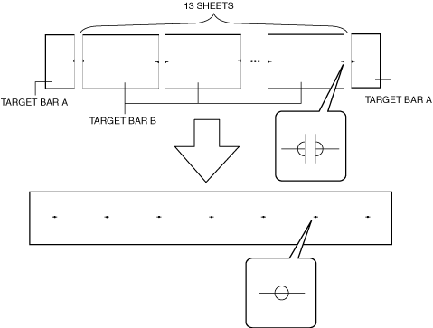
15. Print out 13 sheets of the following target paper B without using scaling.
-
Note
-
• If the target paper cannot be printed, follow the dimensions shown in Step 18 to make target sheets.
16. Cut the target papers along the frame.
17. Align the center marks as shown in the figure, and tape them together using adhesive tape to the back side to make an adjustment target bar.
-
Caution
-
• When taping the target papers together, if adhesive tape is affixed to the front side of the target papers, light may reflect off the tape and it may cause a poor adjustment or the precision may worsen. Affix adhesive tape to the back side of the target papers when taping them together.
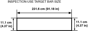
18. Verify that the dimensions of the taped target papers are as indicated in the figure.
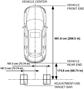
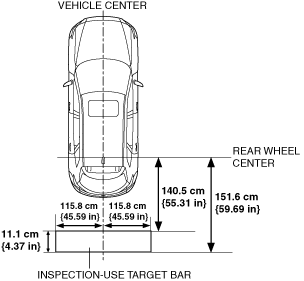
19. Attach the target bars for adjustment to the position (floor surface) shown in the figure.
-
Caution
-
• If the installation position of an adjustment target bar is deviated, the camera optical axis may not set to the correct position. The margin of error in the installation position of an adjustment target bar is 5 mm {0.2 in} or less.
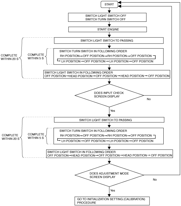
20. Launch the initialization (calibration) mode using the following procedure.
-
Caution
-
• If the initialization (calibration) is not implemented, the initialization mode is force-launched when the ignition is switched ON, and the adjustment mode No.1 screen is displayed, therefore, the procedure shown in the figure is not required.
-
Note
-
• The initialization (calibration) mode is launched using the light switch and turn switch. The operation method for the light switch and turn switch, refer to the switch operation method. (See
Switch Operation Method.)
-
Note
-
• If it does not change to the adjustment mode No.1 screen and the screen turns black, a malfunction in the rear mount camera can be considered. Verify the connection status of the rear mount camera.
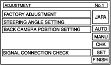
21. Select the adjustment mode No.1 screen MANU.
-
Note
-
• The initialization (calibration) is not available for the touch panel operation. Select the screen using the turn switch or light switch as follows. The operation method for the light switch and turn switch, refer to the switch operation method. (See
Switch Operation Method.)
|
Screen cursor
|
Used switch
|
Switch operation
|
|
Move to right
|
turn switch
|
RH position
|
|
Move to left
|
turn switch
|
LH position
|
|
Selects (decides)
|
light switch
|
Passing position
|
22. Select the adjustment mode No.1 screen FACTORY ADJUSTMENT.
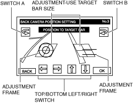
23. Operate switch A, B and the up/down switch of the back camera optical axis adjustment screen and center the target bar for adjustment in the adjustment frame.
24. Select the back camera optical axis adjustment No.3 screen OK.
-
Note
-
• The rear mount camera stores the adjustment value after OK is selected. The image at the rear of the vehicle taken by the rear mount camera is displayed on the screen while the adjustment value is stored. When storage of the adjustment value is completed, the screen switches to the adjustment mode No.1 screen.
25. Verify that the adjustment mode No.1 screen is displayed.
-
• If it does not display, repeat procedure from Step 20.
• If the adjustment mode No.1 screen is not displayed even if the procedure is repeated from Step 20, a rear mount camera malfunction can be considered. Replace the rear mount camera and perform the initialization again (calibration).
26. Peel off the attached target bars for the adjustment in Step 2 and attach the target bar for the inspection to the position (floor surface) shown in the figure.
-
Caution
-
• If the installation position of an inspection target bar is deviated, the camera optical axis may not set to the correct position. The margin of error in the installation position of an inspection target bar is 5 mm {0.2 in} or less.
27. Select the adjustment mode No.1 screen CHK.
28. Verify that the parking brake is applied correctly.
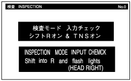
29. Input the following inspection password after displaying the inspection screen.
-
• Shift the selector lever to the R position.
• Switch the light switch from the OFF position to the TNS position, and then OFF again.
-
Warning
-
• When inputting the inspection password, keep the brake pedal depressed so that the vehicle does not unexpectedly move and cause an accident.
30. Verify that the applicable vehicle specification is displayed on the inspection screen.
-
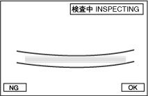
31. Verify that the distance reference line for the inspection is above the inspection-use target marker, and select OK.
-
• If it is not above the inspection-use target marker, select NG and perform the initialization again.
32. Switch the ignition OFF (LOCK).
33. Launch the initialization (calibration) mode using the following procedure.
-
Note
-
• The initialization (calibration) mode is launched using the light switch and turn switch. The operation method for the light switch and turn switch, refer to the switch operation method. (See
Switch Operation Method.)
-
Note
-
• If it does not change to the adjustment mode No.1 screen and the screen turns black, a malfunction in the rear mount camera can be considered. Verify the connection status of the rear mount camera.
34. Verify that the adjustment No.1 screen FACTORY ADJUSTMENT item is not displayed in black.
-
Note
-
• Adjustment items that have been completed are displayed in black on the screen. If the factory adjustment item is displayed in green, perform the procedure from Step 20 again because the adjustment has not been completed.
35. Shift the selector lever to the R position.
-
Warning
-
• When operating the selector lever, keep the brake pedal depressed so that the vehicle does not unexpectedly move and cause an accident.
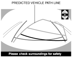
36. Turn the steering wheel left and right until it locks, and verify that the predicted vehicle path line movement is synchronized to the operation.
-
• If the predicted vehicle path lines do not link, or they do not move prior to locking the steering wheel, the steering angle signal will not be received correctly, therefore, perform signal connection verification. (See
Guide Line Display Setting Change.)
-
Caution
-
• The predicted vehicle track is displayed only if the guide line display setting is SET1. If the guide line display setting is other than SET1, change the guide line display setting. (See
Guide Line Display Setting Change.)
37. Launch the initialization (calibration) mode using the following procedure.
-
Note
-
• The initialization (calibration) mode is launched using the light switch and turn switch. The operation method for the light switch and turn switch, refer to the switch operation method. (See
Switch Operation Method.)
-
Note
-
• If it does not change to the adjustment mode No.1 screen and the screen turns black, a malfunction in the rear mount camera can be considered. Verify the connection status of the rear mount camera.
38. Select the adjustment mode No.1 screen SIGNAL CONNECTION CHECK.
-
Note
-
• The initialization (calibration) is not available for the touch panel operation. Select the screen using the turn switch or light switch as follows. The operation method for the light switch and turn switch, refer to the switch operation method. (See
Switch Operation Method.)
|
Screen cursor
|
Used switch
|
Switch operation
|
|
Move to right
|
turn switch
|
RH position
|
|
Move to left
|
turn switch
|
LH position
|
|
Selects (decides)
|
light switch
|
Passing position
|
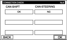
39. Verify the input signal status displayed on the screen.
|
Item
|
OPERATION
|
|
CAN shift signal
|
The signal connection verification is performed automatically.
|
|
CAN Steering angle
|
The signal connection verification is performed automatically.
|
-
• Items displaying OK: Signal input normal
• Items not displaying OK: Verify connection status of vehicle wiring harnesses, parts and the CAN signal communication status.
Guide Line Display Setting Change
-
Note
-
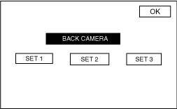
• The setting for the guide lines displayed in the image from the rear mount camera can be changed as follows:
-
? predicted vehicle track display (SET1)
? Fixed line display (SET2)
? No guide line display (SET3)
• The guide line setting can only be changed if the initialization (calibration) has been completed.
Changing to predicted vehicle track display
1. Launch the initialization (calibration) mode using the following procedure.
-
Note
-
• The initialization (calibration) mode is launched using the light switch and turn switch. The operation method for the light switch and turn switch, refer to the switch operation method. (See
Switch Operation Method.)
-
Note
-
• If it does not change to the adjustment mode No.1 screen and the screen turns black, a malfunction in the rear mount camera can be considered. Verify the connection status of the rear mount camera.
2. Select the adjustment mode No.1 screen SET.
-
Note
-
• The initialization (calibration) is not available for the touch panel operation. Select the screen using the turn switch or light switch as follows. The operation method for the light switch and turn switch, refer to the switch operation method. (See
Switch Operation Method.)
|
Screen cursor
|
Used switch
|
Switch operation
|
|
Move to right
|
turn switch
|
RH position
|
|
Move to left
|
turn switch
|
LH position
|
|
Selects (decides)
|
light switch
|
Passing position
|
3. Select setting screen SET1.
-
• Verify that "SET1" on the setting screen is displayed in red.
4. Select setting screen OK.
5. Select the adjustment mode No.1 screen FINISH.
Guide lines not displayed
1. Launch the initialization (calibration) mode using the following procedure.
-
Note
-
• The initialization (calibration) mode is launched using the light switch and turn switch. The operation method for the light switch and turn switch, refer to the switch operation method. (See
Switch Operation Method.)
-
Note
-
• If it does not change to the adjustment mode No.1 screen and the screen turns black, a malfunction in the rear mount camera can be considered. Verify the connection status of the rear mount camera.
2. Select the adjustment mode No.1 screen SET.
-
Note
-
• The initialization (calibration) is not available for the touch panel operation. Select the screen using the turn switch or light switch as follows. The operation method for the light switch and turn switch, refer to the switch operation method. (See
Switch Operation Method.)
|
Screen cursor
|
Used switch
|
Switch operation
|
|
Move to right
|
turn switch
|
RH position
|
|
Move to left
|
turn switch
|
LH position
|
|
Selects (decides)
|
light switch
|
Passing position
|
3. Select setting screen SET2.
-
• Verify that "SET2" on the setting screen is displayed in red.
4. Select setting screen OK.
5. Select the adjustment mode No.1 screen FINISH.
Changing to display without guide lines
1. Launch the initialization (calibration) mode using the following procedure.
-
Note
-
• The initialization (calibration) mode is launched using the light switch and turn switch. The operation method for the light switch and turn switch, refer to the switch operation method. (See
Switch Operation Method.)
-
Note
-
• If it does not change to the adjustment mode No.1 screen and the screen turns black, a malfunction in the rear mount camera can be considered. Verify the connection status of the rear mount camera.
2. Select the adjustment mode No.1 screen SET.
-
Note
-
• The initialization (calibration) is not available for the touch panel operation. Select the screen using the turn switch or light switch as follows. The operation method for the light switch and turn switch, refer to the switch operation method. (See
Switch Operation Method.)
|
Screen cursor
|
Used switch
|
Switch operation
|
|
Move to right
|
turn switch
|
RH position
|
|
Move to left
|
turn switch
|
LH position
|
|
Selects (decides)
|
light switch
|
Passing position
|
3. Select setting screen SET3.
-
• Verify that "SET3" on the setting screen is displayed in red.
4. Select setting screen OK.
5. Select the adjustment mode No.1 screen FINISH.
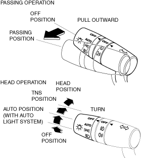
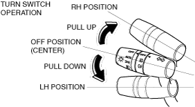
Switch Operation Method
• The operation method for the light switch and turn switch is indicated as follows:
Light switch operation method
Turn switch operation method