49 L067 001
Reflector
49 L067 002
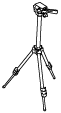
Tripod
49 L067 003
Plum-bob

RADAR UNIT AIMING
id152000004600
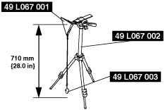
Special Service Tool (SST)
|
49 L067 001
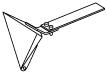
Reflector
|
|
49 L067 002
Tripod
|
|
49 L067 003
Plum-bob
|
|
1. Park the vehicle on level ground.
ac9uuw00007913
|
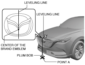
2. Adjust the SST (plum-bob) so that it is aligned with the center of the brand emblem, determine the center position at the front of the vehicle, and mark the center position (point A) on the floor surface.
ac9uuw00007914
|
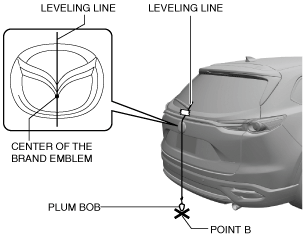
3. Adjust the SST (plum-bob) so that it is aligned with the center of the brand emblem, determine the center position at the rear of the vehicle, and mark the center position (point B) on the floor surface.
ac9uuw00007915
|
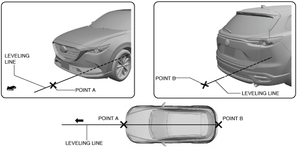
4. Secure the end of the leveling line over point B.
ac9uuw00007916
|
5. Pull the unsecured end of the leveling line over the vehicle and to the front and adjust it so that it passes over point A.
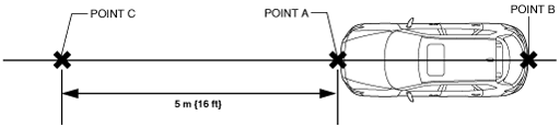
6. Mark the line (position A) at the point 5 m {16 ft} from point A and in the direction forward of the vehicle.
ac9uuw00007917
|
7. Install the SST (reflector and plum bob) to the SST (tripod).
8. Adjust so that the height of the SST (reflector) from the floor surface is 710 mm {28.0 in}.
am6zzw00011465
|
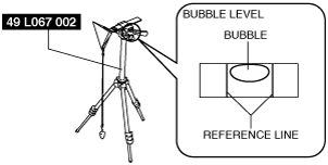
9. Level the SST (reflector) by adjusting the leveling bubble on the SST (tripod) so that it is centered on the bubble reference line.
am6zzw00011466
|
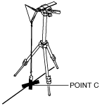
10. Set the SST (stand) with the SST (plum-bob) and the marking aligned.
am6zzw00011467
|
11. Visually inspect the surfaces of the radar unit and the radiator grille ornament for the following:
12. Connect the M-MDS to the DLC-2.
13. After the vehicle is identified, select the following items from the initialization screen of the M-MDS.
14. Perform the aiming adjustment following the instructions on the screen.
15. If "Aiming has been unsuccessful." Is displayed on the screen, repair according to the error code in the following chart.
|
Error code |
Item |
Possible cause |
Inspection item (s) |
|---|---|---|---|
|
Code 1
|
Improper target position
|
• SST (reflector) installation mistake
• Marking setting mistake
• Improper installation of radar unit
• Radar unit malfunction
|
• SST (reflector) installation condition
• Marking setting condition (SST string)
• Radar unit installation condition and installation part condition
• Applicable DTC troubleshooting
|
|
Code 2
|
Improper target angle
|
• SST (reflector) installation mistake
• Marking setting mistake
• Improper installation of radar unit
• Radar unit malfunction
|
• SST (reflector) installation condition
• Marking setting condition (SST string)
• Radar unit installation condition and installation part condition
• Applicable DTC troubleshooting
|
|
Code 3
|
Multiple targets
|
• There is reflective object on area around SST (reflector) which could become a possible target
• Radar unit malfunction
|
• Remove reflective object on area around SST (reflector) which could become a possible target
• Applicable DTC troubleshooting
|
|
Code 4
|
Target moves
|
• SST (reflector) moves (within radar unit reception range) during aiming
• Radar unit malfunction
|
• SST (reflector) installation condition
• Applicable DTC troubleshooting
|
|
Code 5
|
No target
|
• Voltage supplied to radar unit is out of specification
• Aiming performed under out-of-specification temperature
• Dirt is adhering to radar unit or radiator grille ornament
• Dirt is adhering to SST (reflector)
• SST (reflector) is deformed
• SST (reflector) does not exist (within radar unit reception range) during aiming
• Radar unit malfunction
|
• Radar unit supply voltage inspection (approx. 9.5—15.5 V)
• Ambient temperature verification (approx. -30—60 °C {-22—140 °F})
• Remove dirt from radar senor or radiator grille ornament surface
• Remove dirt from SST (reflector)
• Replace SST (reflector)
• SST (reflector) installation condition
• Applicable DTC troubleshooting
|
|
Code 7
|
Vehicle condition malfunction
|
• Vehicle moves during aiming (vehicle door opening/closing, getting on vehicle) (change in wheel speed)
• Radar unit malfunction
|
• Verification of selector lever position (in P position)
|