 |
ac9wzw00005512
DTC P0138:00 [PCM (SKYACTIV-G 2.5T)]
id0102s8702600
Details On DTCs
|
DESCRIPTION |
HO2S circuit high input |
|
|---|---|---|
|
DETECTION CONDITION
|
Determination conditions
|
• A condition in which the HO2S input voltage exceeds the specified value continues for the specified period.
|
|
Preconditions
|
• Not applicable
|
|
|
Malfunction determination period
|
• 5 s period
|
|
|
Drive cycle
|
• 2
|
|
|
Self test type
|
• CMDTC self test, KOEO self test, KOER self test
|
|
|
Sensor used
|
• HO2S
|
|
|
FAIL-SAFE FUNCTION
|
• Not applicable
|
|
|
VEHICLE STATUS WHEN DTCs ARE OUTPUT
|
• Illuminates check engine light.
|
|
|
POSSIBLE CAUSE
|
• HO2S connector or terminals malfunction
• PCM connector or terminals malfunction
• Short to power supply in wiring harness between the following terminals:
• HO2S malfunction
• PCM malfunction
|
|
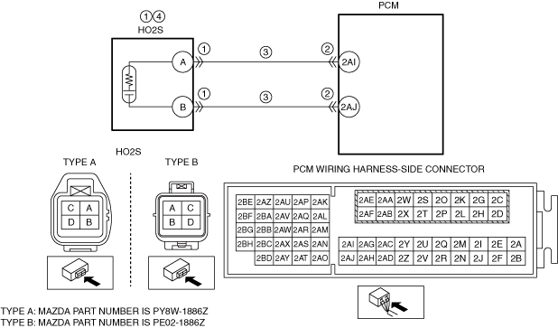
System Wiring Diagram
ac9wzw00005512
|
Function Explanation (DTC Detection Outline)
Repeatability Verification Procedure
PID Item/Simulation Item Used In Diagnosis
Function Inspection Using M-MDS
|
STEP |
INSPECTION |
RESULTS |
ACTION |
|---|---|---|---|
|
1
|
PURPOSE: VERIFY RELATED SERVICE INFORMATION AVAILABILITY
• Verify related Service Information availability.
• Is any related Service Information available?
|
Yes
|
Perform repair or diagnosis according to the available Service Information.
• If the vehicle is not repaired, go to the next step.
|
|
No
|
Go to the next step.
|
||
|
2
|
PURPOSE: RECORD FREEZE FRAME DATA/SNAPSHOT DATA AND DIAGNOSTIC MONITORING TEST RESULTS TO UTILIZE WITH REPEATABILITY VERIFICATION
• Record the FREEZE FRAME DATA/snapshot data and DIAGNOSTIC MONITORING TEST RESULTS (A/F sensor, HO2S related) on the repair order.
|
—
|
Go to the troubleshooting procedure to perform the procedure from Step 1.
|
Troubleshooting Diagnostic Procedure
|
STEP |
INSPECTION |
RESULTS |
ACTION |
|---|---|---|---|
|
1
|
PURPOSE: INSPECT HO2S CONNECTOR CONDITION
• Switch the ignition off.
• Disconnect the HO2S connector.
• Inspect for poor connection (such as damaged/pulled-out pins, corrosion).
• Is there any malfunction?
|
Yes
|
Repair or replace the connector and/or terminals, then go to Step 5.
|
|
No
|
Go to the next step.
|
||
|
2
|
PURPOSE: INSPECT PCM CONNECTOR CONDITION
• Disconnect the PCM connector.
• Inspect for poor connection (such as damaged/pulled-out pins, corrosion).
• Is there any malfunction?
|
Yes
|
Repair or replace the connector and/or terminals, then go to Step 5.
|
|
No
|
Go to the next step.
|
||
|
3
|
PURPOSE: INSPECT HO2S CIRCUIT FOR SHORT TO POWER SUPPLY
• Verify that the HO2S and PCM connectors are disconnected.
• Switch the ignition ON (engine off).
• Measure the voltage at the following terminals (wiring harness-side):
• Is the voltage 0 V?
|
Yes
|
Go to the next step.
|
|
No
|
Refer to the wiring diagram and verify whether or not there is a common connector between the following terminals:
• HO2S terminal A—PCM terminal 2AI
• HO2S terminal B—PCM terminal 2AJ
If there is a common connector:
• Determine the malfunctioning part by inspecting the common connector and the terminal for corrosion, damage, or pin disconnection, and the common wiring harness for a short to power supply.
• Repair or replace the malfunctioning part.
If there is no common connector:
• Repair or replace the wiring harness which has a short to power supply.
Go to Step 5.
|
||
|
4
|
PURPOSE: DETERMINE INTEGRITY OF HO2S
• Reconnect all disconnected connectors.
• Inspect the HO2S.
• Is there any malfunction?
|
Yes
|
Replace the HO2S, then go to the next step.
|
|
No
|
Go to the next step.
|
||
|
5
|
PURPOSE: VERIFICATION OF VEHICLE REPAIR COMPLETION
• Always reconnect all disconnected connectors.
• Clear the DTC from the PCM memory using the M-MDS.
• Perform the KOEO or KOER self test.
• Is the PENDING CODE for this DTC present?
|
Yes
|
Repeat the inspection from Step 1.
• If the malfunction recurs, replace the PCM.
Go to the next step.
|
|
No
|
Go to the next step.
|
||
|
6
|
PURPOSE: VERIFY IF THERE IS ANY OTHER MALFUNCTION
• Is any other DTC or pending code stored?
|
Yes
|
Go to the applicable DTC inspection.
|
|
No
|
DTC troubleshooting completed.
|