 |
ac9uuw00006013
PCM REMOVAL/INSTALLATION [SKYACTIV-G 2.5T]
id0140h0802400
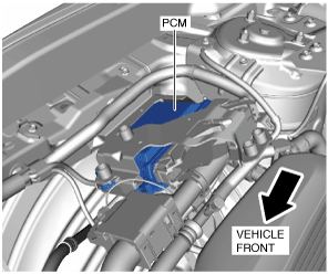
PCM Removal/Installation
Without set bolt
ac9uuw00006013
|
1. Disconnect the negative battery terminal. (See NEGATIVE BATTERY TERMINAL DISCONNECTION/CONNECTION.)
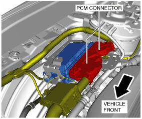
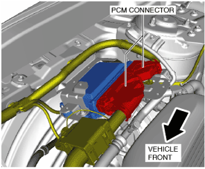
2. Disconnect the PCM connectors. (See PCM Connector Connection Note.)
ac9wzw00003553
|
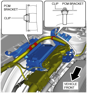
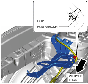
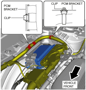
3. Remove the clips from the PCM bracket.
ac9uuw00006015
|
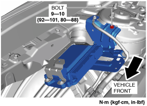
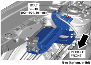
4. Loosen the bolt.
ac9wzw00003554
|
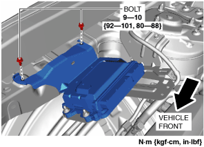
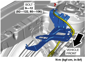
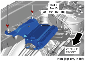
5. Remove the bolts. (See PCM Bracket Installation Note.)
ac9wzw00003555
|
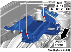
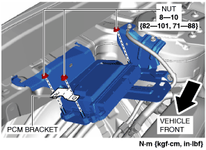
6. Remove the nuts.
ac9wzw00003556
|
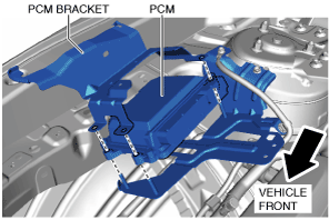
7. Remove the PCM bracket. (See PCM Bracket Temporary Installation Note.)
am3zzw00017500
|
8. Remove the PCM.
9. Remove the bolt.
ac9wzw00003557
|
10. Remove the clip from the PCM bracket.
ac9uuw00006020
|
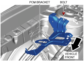
11. Remove the bolt. (See PCM Bracket Installation Note.)
ac9uuw00006021
|
12. Remove the PCM bracket.
13. Install in the reverse order of removal.
14. When replacing the PCM on the vehicles, perform the following:
With set bolt
ac9uuw00006100
|
1. Disconnect the negative battery terminal. (See NEGATIVE BATTERY TERMINAL DISCONNECTION/CONNECTION.)
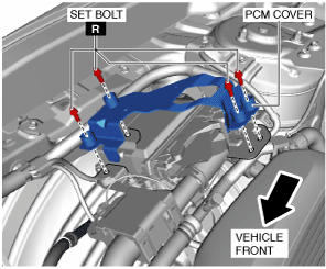
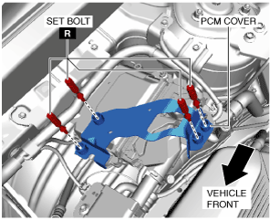
2. Remove the set bolts. (See Set Bolt Removal Note.) (See Set Bolt Installation Note.)
ac9wzw00003384
|
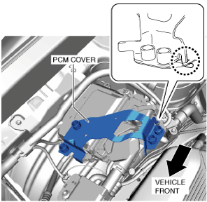
3. Remove the PCM cover. (See PCM Cover Installation Note.)
4. Disconnect the PCM connectors. (See PCM Connector Connection Note.)
ac9wzw00003385
|
5. Remove the clips from the PCM bracket.
ac9wzw00003386
|
6. Loosen the bolt.
ac9wzw00003387
|
7. Remove the bolts. (See PCM Bracket Installation Note.)
ac9uuw00006105
|
8. Remove the nuts.
ac9wzw00003388
|
9. Remove the PCM bracket.
10. Remove the PCM bracket. (See PCM Bracket Temporary Installation Note.)
ac9wzw00003389
|
11. Remove the PCM.
12. Remove the bolt.
ac9wzw00003557
|
13. Remove the clip from the PCM bracket.
ac9uuw00006020
|
14. Remove the bolt. (See PCM Bracket Installation Note.)
ac9uuw00006021
|
15. Remove the PCM bracket.
16. Install in the reverse order of removal.
17. When replacing the PCM on the vehicles, perform the following:
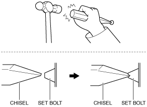
Set Bolt Removal Note
1. Using a chisel and a hammer, cut a groove on the head of the set bolt so that a screwdriver can be inserted.
2. Loose the set bolt using an impact screwdriver or pliers.
ac9wzw00003390
|
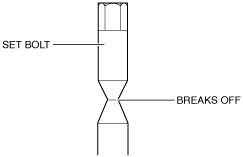
Set Bolt Installation Note
1. Install a new set bolt and tighten it until the neck of the bolt breaks off.
ac9wzw00003391
|
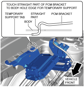
PCM Bracket Temporary Installation Note
1. Install the PCM bracket as shown in the figure.
ac9uuw00006022
|
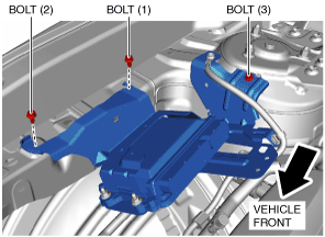
PCM Bracket Installation Note
1. Install the bolts using the following procedure:
ac9uuw00006023
|
PCM Cover Installation Note
1. Install the PCM cover as shown in the figure.
am3zzw00017501
|
2. Temporarily tighten the four bolts, then completely tighten them.
ac9wzw00003392
|
PCM Connector Connection Note
am2zzw00011991
|
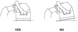
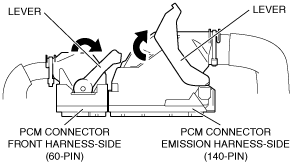
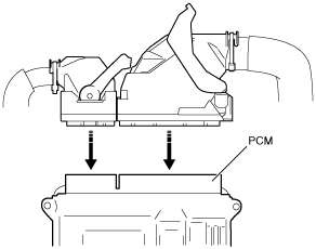
1. Set the PCM connector lever to the position shown in the figure.
am2zzw00011992
|
2. Align the PCM connector straight against the connection surface.
adejjw00012311
|
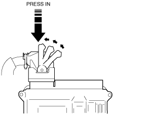
3. Insert the PCM connector straight and press it in until the lever moves up naturally. (Front harness-side connector)
ac9uuw00006024
|
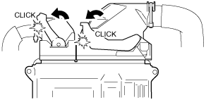
4. Press the PCM connector lever until a click sound is heard.
am2zzw00011994
|