 |
ac9uuw00006382
ENGINE OIL SOLENOID VALVE REMOVAL/INSTALLATION [SKYACTIV-G 2.5T]
id0111q8003000
1. Disconnect the negative battery terminal. (See NEGATIVE BATTERY TERMINAL DISCONNECTION/CONNECTION.)
2. Remove the front under cover No.2. (See FRONT UNDER COVER No.2 REMOVAL/INSTALLATION.)
3. Remove the front wheel and tire. (RH) (See WHEEL AND TIRE REMOVAL/INSTALLATION.)
4. Remove the front splash shield (RH). (See FRONT SPLASH SHIELD REMOVAL/INSTALLATION.)
5. Remove the water pump drive belt with the generator drive belt still installed and set it aside. (See DRIVE BELT REMOVAL/INSTALLATION [SKYACTIV-G 2.5T].)
6. Remove the engine oil pressure sensor/engine oil temperature sensor. (See ENGINE OIL PRESSURE SENSOR/ENGINE OIL TEMPERATURE SENSOR REMOVAL/INSTALLATION [SKYACTIV-G 2.5T].)
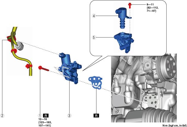
7. Remove in the order indicated in the table.
8. Install in the reverse order of removal.
9. Start the engine and confirm that there is no oil leakage.
ac9uuw00006382
|
|
1
|
Bolt
(See Bolt Removal Note.)
(See Bolt Installation Note.)
|
|
2
|
Engine oil solenoid valve connector
|
|
3
|
Engine oil solenoid valve component
|
|
4
|
Engine oil solenoid valve
|
|
5
|
Spacer
|
Bolt Removal Note
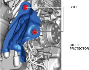
1. Cover the area around the engine oil solenoid valve with a cloth because a small amount of engine oil will leak from the engine oil solenoid valve installation area.
2. Remove the bolts shown in the figure.
ac9uuw00006383
|
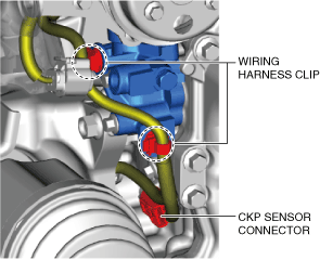
3. Remove the wiring harness clips and connector shown in the figure.
ac9uuw00006384
|
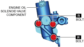
4. Remove the bolts shown in the figure.
ac9uuw00006385
|
Engine Oil Solenoid Valve Connector Disconnecting Note
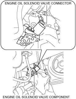
1. Pull out the engine oil solenoid valve component with the connector connected as shown in the figure.
ac9uuw00006386
|
2. Disconnect the engine oil solenoid valve connector.
Bolt Installation Note
1. After tightening the three bolts shown in the figure, tighten the first tightened bolt to the specified tightening torque again.
ac9uuw00006385
|
2. Install the wiring harness clips and connector shown in the figure.
ac9uuw00006384
|
3. Tighten the bolts shown in the figure.
ac9uuw00006383
|