 |
am3uuw00007248
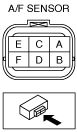
AIR FUEL RATIO (A/F) SENSOR INSPECTION [SKYACTIV-G 2.5T]
id0140h0899600
PID/DATA Monitor Inspection (A/F Sensor)
1. Connect the M-MDS to the DLC-2.
2. Start the engine and warm it up completely.
3. Access the following PIDs using the M-MDS. (See ON-BOARD DIAGNOSTIC TEST [PCM (SKYACTIV-G 2.5T)].)
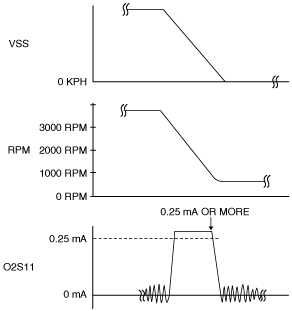
4. Drive the vehicle and decelerate the engine speed by releasing the accelerator pedal fully when the engine speed is 3,000 rpm or more.
5. Verify that the A/F sensor output current (PID: O2S11) is 0.25 mA or more while decelerating as shown in the figure.
am3uuw00007248
|
Resistance Inspection (A/F Sensor Heater)
1. Disconnect the negative battery terminal. (See NEGATIVE BATTERY TERMINAL DISCONNECTION/CONNECTION.)
2. Set the PCM component aside. (See AIR FUEL RATIO (A/F) SENSOR REMOVAL/INSTALLATION [SKYACTIV-G 2.5T].)
3. Disconnect the A/F sensor connector.
4. Measure the resistance between A/F sensor terminals A and E.
ac9uuw00007711
|