AIR FUEL RATIO (A/F) SENSOR REMOVAL/INSTALLATION [SKYACTIV-G 2.5T]
id0140h0899700
Special Service Tool (SST)
|
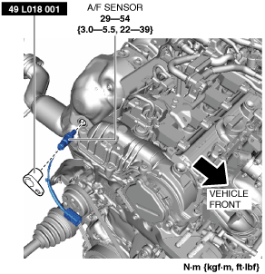
49 L018 001
O2 sensor wrench
|
 |
—
|
—
|
-
Warning
-
• A hot engine and exhaust system can cause severe burns. Turn off the engine and wait until they are cool before removing the exhaust system.
-
Caution
-
• Do not allow flammable objects such as the taping for bundling the wiring harness to come into contact with the exhaust system such as the exhaust manifold and silencer which reach high temperatures. Otherwise, it could cause fire damage.
1. Disconnect the negative battery terminal. (See NEGATIVE BATTERY TERMINAL DISCONNECTION/CONNECTION.)
2. Remove the following parts:
- (1) Plug hole plate (See PLUG HOLE PLATE REMOVAL/INSTALLATION [SKYACTIV-G 2.5T].)
-
- (2) Cowl panel (See COWL PANEL REMOVAL/INSTALLATION.)
-
- (3) Front under cover No.2 (See FRONT UNDER COVER No.2 REMOVAL/INSTALLATION.)
-
- (4) Insulator (See EXHAUST SYSTEM REMOVAL/INSTALLATION [SKYACTIV-G 2.5T].)
-
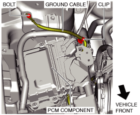
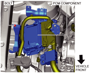
3. Set the PCM component aside using the following procedure: (See PCM Component Installation Note.)
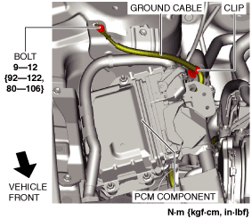
- (1) Remove the clip and bolt shown in the figure and set the ground cable aside.
-
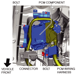
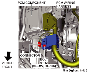
- (2) Remove the bolts and connector shown in the figure.
-
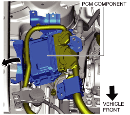
- (3) Move the PCM component in the direction of the arrow shown in the figure and set it aside with the PCM connectors connected.
-
4. Disconnect the A/F sensor connector.
5. Remove the A/F sensor using the SST.
6. Install in the reverse order of removal.
PCM Component Installation Note
1. Install the PCM component using the following procedure:
- (1) Return the PCM component that was set aside to its original position.
-
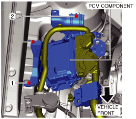
- (2) Temporarily tighten the bolt shown in the figure.
-
- (3) Tighten the PCM component installation bolts in the order shown in the figure.
-
-
Tightening torque
-
9—10 N·m {92—101 kgf·cm, 80—88 in·lbf}
- (4) Install the wiring harness protector and connector.
-
- (5) Install the ground cable shown in the figure.
-