|
1
|
INSPECT START STOP UNIT CONNECTOR CONDITION
• Switch the ignition off.
• Disconnect the negative battery terminal.
• Disconnect the start stop unit connector.
• Inspect the connector engagement and connection condition and inspect the terminals for damage, deformation, corrosion, or disconnection.
• Is the connector normal?
|
Yes
|
Go to the next step.
|
|
No
|
Repair or replace the connector, then go to Step 7.
|
|
2
|
INSPECT INSTRUMENT CLUSTER CONNECTOR
• Disconnect the instrument cluster connector.
• Inspect the connector engagement and connection condition and inspect the terminals for damage, deformation, corrosion, or disconnection.
• Is the connector normal?
|
Yes
|
Go to the next step.
|
|
No
|
Repair or replace the connector, then go to Step 7.
|
|
3
|
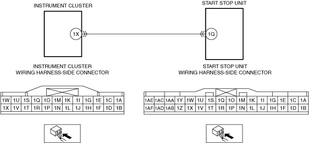
INSPECT WIRING HARNESS BETWEEN INSTRUMENT CLUSTER AND START STOP UNIT FOR SHORT TO GROUND
• Verify that the instrument cluster and start stop unit connectors are disconnected.
• Inspect for continuity between start stop unit terminal 1Q (wiring harness-side) and body ground.
• Is there continuity?
|
Yes
|
Refer to the wiring diagram and verify whether or not there is a common connector between instrument cluster terminal 1X and start stop unit terminal 1Q.
If there is a common connector:
• Determine the malfunctioning part by inspecting the common connector and the terminal for corrosion, damage, or pin disconnection, and the common wiring harness for a short to ground.
• Repair or replace the malfunctioning part.
If there is no common connector:
• Repair or replace the wiring harness which has a short to ground.
Go to Step 7.
|
|
No
|
Go to the next step.
|
|
4
|
INSPECT WIRING HARNESS BETWEEN INSTRUMENT CLUSTER AND START STOP UNIT FOR SHORT TO POWER SUPPLY
• Verify that the instrument cluster and start stop unit connectors are disconnected.
• Connect the negative battery terminal.
• Switch the ignition ON (engine off or on).
• Measure the voltage at the start stop unit terminal 1Q (wiring harness-side).
• Is the voltage 0 V?
|
Yes
|
Go to the next step.
|
|
No
|
Refer to the wiring diagram and verify whether or not there is a common connector between instrument cluster terminal 1X and start stop unit terminal 1Q.
If there is a common connector:
• Determine the malfunctioning part by inspecting the common connector and the terminal for corrosion, damage, or pin disconnection, and the common wiring harness for a short to power supply.
• Repair or replace the malfunctioning part.
If there is no common connector:
• Repair or replace the wiring harness which has a short to power supply.
Go to Step 7.
|
|
5
|
INSPECT WIRING HARNESS BETWEEN INSTRUMENT CLUSTER AND START STOP UNIT FOR OPEN CIRCUIT
• Switch the ignition off.
• Disconnect the negative battery terminal.
• Verify that the instrument cluster and start stop unit connectors are disconnected.
• Inspect the wiring harness for continuity between instrument cluster terminal 1X (wiring harness-side) and start stop unit terminal 1Q (wiring harness-side).
• Is there continuity?
|
Yes
|
Go to the next step.
|
|
No
|
Refer to the wiring diagram and verify whether or not there is a common connector between instrument cluster terminal 1X and start stop unit terminal 1Q.
If there is a common connector:
• Determine the malfunctioning part by inspecting the common connector and the terminal for corrosion, damage, or pin disconnection, and the common wiring harness for an open circuit.
• Repair or replace the malfunctioning part.
If there is no common connector:
• Repair or replace the wiring harness which has an open circuit.
Go to Step 7.
|
|
6
|
VERIFY IF MALFUNCTIONING LOCATION IS START STOP UNIT DEPENDING ON REPEATABILITY
• Always reconnect all disconnected connectors.
• Connect the negative battery terminal.
• Clear the DTC for the instrument cluster using the M-MDS.
• Retrieve the instrument cluster DTCs using the M-MDS.
• Is the same Pending DTC present?
|
Yes
|
Replace the start stop unit, then go to the next step.
|
|
No
|
Go to Step 8.
|
|
7
|
VERIFY THAT REPAIRS HAVE BEEN COMPLETED
• Always reconnect all disconnected connectors.
• Connect the negative battery terminal.
• Clear the DTC for the instrument cluster using the M-MDS.
• Retrieve the instrument cluster DTCs using the M-MDS.
• Is the same Pending DTC present?
|
Yes
|
Repeat the inspection from Step 1.
• If the malfunction recurs, replace the instrument cluster.
Go to the next step.
|
|
No
|
Go to the next step.
|
|
8
|
VERIFY IF OTHER DTCs DISPLAYED
• Are any other DTCs displayed?
|
Yes
|
Repair or replace the malfunctioning part according to the applicable DTC troubleshooting.
|
|
No
|
DTC troubleshooting completed.
|