am3zzw00022994
|
-
Caution
-
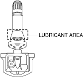
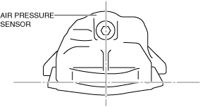
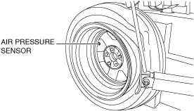
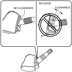
• Set the air pressure sensor to the position shown in the figure so that it does not get damaged.
WHEEL UNIT REMOVAL/INSTALLATION [DIRECT TIRE PRESSURE MONITORING SYSTEM (TPMS) (WITHOUT TPMS SET SWITCH)]
id0212008006f8
Replacement part
|
Sensor housing
Quantity: 1
Location of use: Wheel
|
Valve
Quantity: 1
Location of use: Wheel
|
Snap-In
Removal
1. Remove the valve core and bleed the air from the tire.
2. Break the upper/lower tire bead.
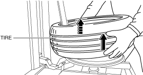
3. Remove the upper/lower bead using the following procedure.
am3zzw00022994
|
am3zzw00022995
|
am3zzw00022996
|
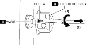
4. Remove the air pressure sensor from the wheel using the following procedure.
am3zzw00022997
|
am3zzw00022998
|
Installation
1. Apply soapy water to the area shown in the figure.
am3zzw00022999
|
2. Remove the cap.
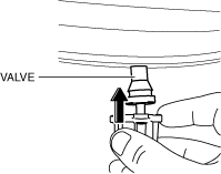
3. Insert the air pressure sensor valve into the wheel valve hole.
am3zzw00023000
|
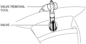
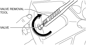
4. Install the valve removal tool to the air pressure sensor valve.
am3zzw00023001
|
5. Pull the air pressure sensor valve straight out of the valve hole as shown in the figure and secure the air pressure sensor to the wheel.
am3zzw00023002
|
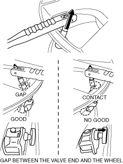
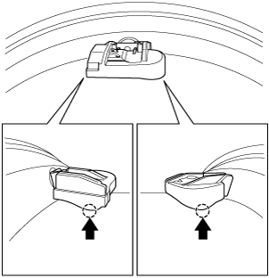
6. Verify that the air pressure sensor is installed parallel to the wheel as shown in the figure.
am3zzw00023003
|
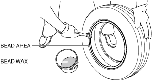
7. Apply bead wax to the tire bead area.
am3zzw00023004
|
8. Install the tire to the wheel using the following procedure.
am3zzw00023005
|
9. Pump air into the tire.
am3zzw00023006
|
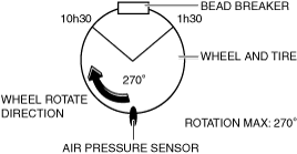
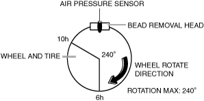
Bead Breaking Note (Method for Rotating Wheel Against Bead Breaker)
1. Install the wheel and tire to the turntable of the tire changer.
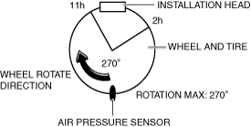
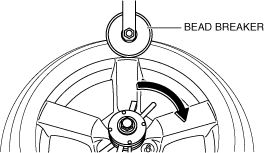
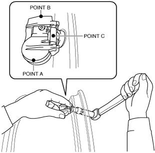
2. Set the bead breaker against the air pressure sensor as shown in the figure.
am3zzw00023007
|
3. Rotate the wheel and break the upper/lower bead.
am3zzw00023008
|
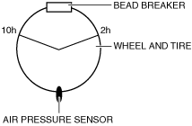
Bead Breaking Note (Method for Securing Wheel)
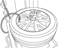
1. Install the wheel and tire to the bead breaker.
2. Set the bead breaker against the air pressure sensor as shown in the figure.
am3zzw00023009
|
3. Break the upper bead.
am3zzw00023010
|
4. Break the lower bead.
am3zzw00023011
|
5. When replacing a wheel unit (s), register the new wheel unit ID (s). (See WHEEL UNIT ID REGISTRATION [DIRECT TIRE PRESSURE MONITORING SYSTEM (TPMS) (WITHOUT TPMS SET SWITCH)].)
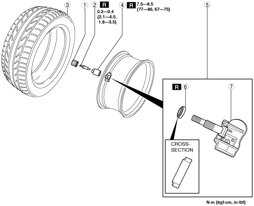
Clamp-In
1. Remove in the order indicated in the table.
2. Install in the reverse order of removal.
3. Install the valve core and valve cap, fill the tire with air.
4. When replacing a wheel unit (s), register the new wheel unit ID (s). (See WHEEL UNIT ID REGISTRATION [DIRECT TIRE PRESSURE MONITORING SYSTEM (TPMS) (WITHOUT TPMS SET SWITCH)].)
amxzzw00003460
|
|
1
|
Valve cap
|
|
2
|
Valve core
(See Valve Core Removal Note.)
|
|
3
|
Tire
(See Tire Removal Note.)
(See Tire Installation Note.)
|
|
4
|
Valve nut
|
|
5
|
Wheel unit component
|
|
6
|
Seal
|
|
7
|
Wheel unit
|
Valve Core Removal Note
1. Remove the valve core of the wheel unit, and bleed the air from the tire.
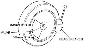
Tire Removal Note
1. Set the bead breaker at the position laterally opposed to the valve.
amxzzw00003461
|
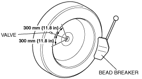
2. Break the bead loose.
3. Break the bead loose on the other side of the wheel.
amxzzw00003462
|
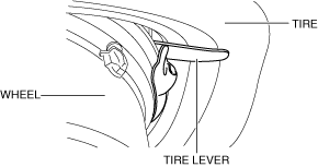
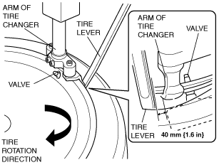
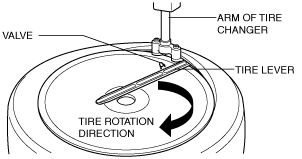
4. Insert the tire lever at the point 40 mm {1.6 in} from the wheel unit in the direction that the tire changer turntable rotates.
amxzzw00003463
|
5. Remove the bead from the wheel.
amxzzw00003464
|
6. For the other side, insert the tire lever at the point of 40 mm {1.6 in} from the wheel unit in the direction that the tire changer turntable rotates, and remove the bead from the wheel.
Tire Installation Note
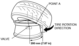
1. Set the tire at point A (200 mm {7.87 in} away from the valve hole), and install the tire.
amxzzw00003465
|
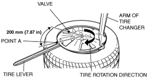
2. Set the tire at point A (200 mm {7.87 in} away from the valve hole).
amxzzw00003466
|
3. Install the tire.
Wheel Unit Component Installation Note
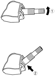
1. Insert the valve into the wheel unit in the order shown in the figure.
am6xuw00003643
|
2. Verify that the valve is installed into the wheel unit completely as shown in the figure.
am6xuw00003645
|
3. Insert the wheel unit valve into the valve hole so that the polyurethane foam side faces the wheel.
4. Temporarily tighten the valve nut by hand.
5. Completely tighten the valve nut using a torque wrench.
amxzzw00003467
|
6. Verify that the wheel unit component is correctly installed.
am6xuw00003624
|
amxzzw00003468
|