DTC C1A90:12/C1A90:16/C1A95:64 [DSC HU/CM]


id040262847200

DTC
C1A90:12
ABS wheel-speed sensor power supply
C1A90:16
C1A95:64
DETECTION CONDITION
•  Malfunction detected in ABS wheel-speed sensor power supply voltage.
FAIL-SAFE FUNCTION
•  Refer to “Fail-safe function table”. (See DTC TABLE [DSC HU/CM].)
POSSIBLE CAUSE
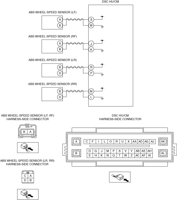
•  Short to ground circuit in wiring harness between ABS wheel-speed sensor (LF) terminal A and DSC HU/CM terminal S
•  Short to ground circuit in wiring harness between ABS wheel-speed sensor (RF) terminal A and DSC HU/CM terminal J
•  Short to ground circuit in wiring harness between ABS wheel-speed sensor (LR) terminal B and DSC HU/CM terminal R
•  Short to ground circuit in wiring harness between ABS wheel-speed sensor (RR) terminal B and DSC HU/CM terminal M
•  Poor connection at each connector
•  DSC HU/CM malfunction

Diagnostic Procedure

Step

Inspection

Action

1
INSPECT ABS WHEEL-SPEED SENSOR POWER CIRCUIT FOR SHORT TO GROUND CIRCUIT
•  Disconnect the ABS wheel-speed sensor connector.
•  Inspect for continuity as followings:
?  ABS wheel-speed sensor (LF) terminal A (wiring harness-side)—body ground
?  ABS wheel-speed sensor (RF) terminal A (wiring harness-side)—body ground
?  ABS wheel-speed sensor (LR) terminal B (wiring harness-side)—body ground
?  ABS wheel-speed sensor (RR) terminal B (wiring harness-side)—body ground
•  Is there continuity?
Yes
Refer to the wiring diagram and verify whether or not there is a common connector in the followings:
•  ABS wheel-speed sensor (LF) terminal A—DSC HU/CM terminal S
•  ABS wheel-speed sensor (RF) terminal A—DSC HU/CM terminal J
•  ABS wheel-speed sensor (LR) terminal B—DSC HU/CM terminal R
•  ABS wheel-speed sensor (RR) terminal B—DSC HU/CM terminal M
If there is a common connector:
•  Determine the malfunctioning part by inspecting the common connector and the terminal for corrosion, damage, or pin disconnection, and the common wiring harness for a short to ground circuit.
•  Repair or replace the malfunctioning part.
If there is no common connector:
•  Repair or replace the wiring harness which has a short to ground circuit.
Go to Step3.
No
Go to the next step.
2
INSPECT ABS WHEEL-SPEED SENSOR POWER CIRCUIT FOR OPEN CIRCUIT
•  Disconnect the ABS wheel-speed sensor connector.
•  Disconnect the DSC HU/CM connector.
•  Inspect for continuity as followings:
?  ABS wheel-speed sensor (LF) terminal A (wiring harness-side)—DSC HU/CM terminal S (wiring harness-side)
?  ABS wheel-speed sensor (RF) terminal A (wiring harness-side)—DSC HU/CM terminal J (wiring harness-side)
?  ABS wheel-speed sensor (LR) terminal B (wiring harness-side)—DSC HU/CM terminal R (wiring harness-side)
?  ABS wheel-speed sensor (RR) terminal B (wiring harness-side)—DSC HU/CM terminal M (wiring harness-side)
•  Is there continuity?
Yes
Go to the next step.
No
Refer to the wiring diagram and verify whether or not there is a common connector in the followings:
•  ABS wheel-speed sensor (LF) terminal A—DSC HU/CM terminal S
•  ABS wheel-speed sensor (RF) terminal A—DSC HU/CM terminal J
•  ABS wheel-speed sensor (LR) terminal B—DSC HU/CM terminal R
•  ABS wheel-speed sensor (RR) terminal B—DSC HU/CM terminal M
If there is a common connector:
•  Determine the malfunctioning part by inspecting the common connector and the terminal for corrosion, damage, or pin disconnection, and the common wiring harness for an open circuit.
•  Repair or replace the malfunctioning part.
If there is no common connector:
•  Repair or replace the wiring harness which has an open circuit.
Go to the next step.
3
VERIFY DTC TROUBLESHOOTING COMPLETED
•  Using the M-MDS, clear the DTC from the DSC HU/CM.
•  Using the M-MDS, perform the DSC HU/CM DTC inspection.
•  Is the same DTC present?
Yes
Repeat the inspection from Step1.
If the malfunction recurs, replace the DSC HU/CM, then go to the next step.
No
Go to the next step.
4
VERIFY NO DTC IS PRESENT
•  Are any DTCs present?
Yes
Go to the applicable DTC inspection.
No
DTC troubleshooting completed.