DSC HU/CM REMOVAL/INSTALLATION
id041500801000
-
Warning
-
• If the DSC HU/CM configuration is not completed, it could result in an unexpected accident due to the DSC being inoperative. If the DSC HU/CM is replaced, always use the automatic configuration function so that the DSC operation conditions are correct.
• If the DSC related parts sensor initialization procedure is not completed, the DSC will not operate properly and it might cause an unexpected accident. Therefore, after replacing or removing the DSC HU/CM, make sure to perform the DSC related parts sensor initialization procedure to insure proper DSC operation.
-
Caution
-
• The internal parts of the DSC HU/CM could be damaged if dropped. Be careful not to drop the DSC HU/CM. Replace the DSC HU/CM if it is subjected to an impact.
• Brake fluid will damage painted surfaces. Be careful not to spill any on painted surfaces. In addition, if there is any brake fluid on the wiring harness, the wire insulation may corrode causing a malfunction such as a short circuit. If brake fluid gets on a painted surface or wiring harness, wash and flush it off completely with water immediately.
-
Note
-
• When the ignition is switched ON or the engine is started after the DSC HU/CM have been replaced, the DSC CM reads data from the instrument cluster via CAN communication to perform automatic configuration.
• The DSC HU/CM prior to replacement stores the vehicle specification information.
• A new DSC HU/CM does not store any vehicle specification information.
• Tighten the brake pipe flare nut using any commercially available flare nut wrench.
1. Disconnect the negative battery terminal. (See NEGATIVE BATTERY TERMINAL DISCONNECTION/CONNECTION.)
2. Remove the plug hole plate. (See PLUG HOLE PLATE REMOVAL/INSTALLATION [SKYACTIV-G 2.5T].)
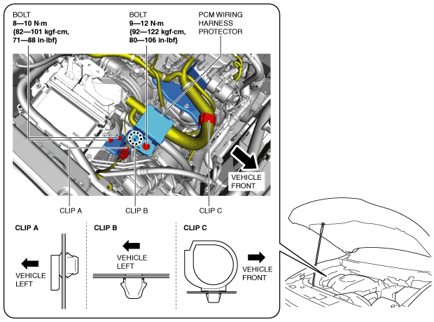
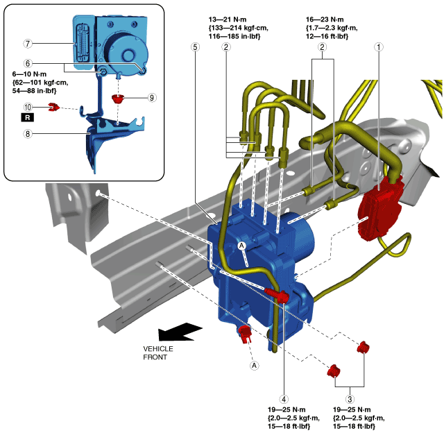
3. Remove the bolts.
4. Remove the clips from the brackets.
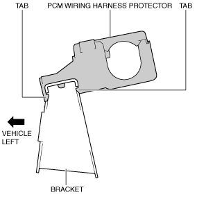
5. Detach the tabs of the PCM wiring harness protector and the bracket, and remove the bracket.
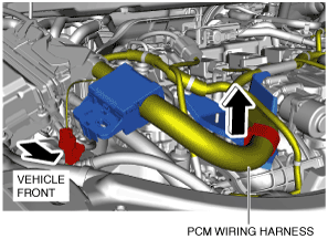
6. Set the PCM wiring harness aside in the direction of the arrow shown in the figure.
7. Remove in the order indicated in the table.
8. Install in the reverse order of removal.
9. After installation, add brake fluid, bleed the air, and inspect for fluid leakage. (See BRAKE FLUID AIR BLEEDING.)
10. If the DSC HU/CM is replaced, perform the auto configuration and the initialization of the sensors for DSC-related parts.
- (1) Switch the ignition ON (engine off or on) and wait for 10 s or more.
-
- (2) Switch the ignition off and wait for 3 s or more.
-
- (3) Switch the ignition ON (engine off or on) and wait for 3 s or more for the DSC HU/CM auto configuration to complete.
-
- (4) Clear the DTC. (See CLEARING DTC [DSC HU/CM].)
-
- (5) Switch the ignition off and wait for 3 s or more.
-
- (6) Switch the ignition ON (engine off or on) and wait for 10 s or more.
-
- (7) Using the M-MDS, verify that DTCs U2300:54/U2300:55/U2300:56/U2300:64 are not displayed.
-
-
- (8) Perform the sensor initialization for the DSC-related parts. (See DSC RELATED PARTS SENSOR INITIALIZATION PROCEDURE.)
-
- (9) Clear the DTC. (See CLEARING DTC [DSC HU/CM].)
-
- (10) Switch the ignition off and wait for 3 s or more.
-
- (11) Switch the ignition ON (engine off or on) and wait for 10 s or more.
-
- (12) Using the M-MDS, verify that DTCs C0044:54/C0061:54/C0062:54/C0063:54 are not displayed.
-
-
|
1
|
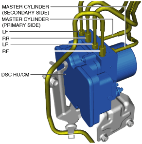
DSC HU/CM connector
|
|
2
|
Brake pipe
|
|
3
|
Nut
|
|
4
|
Bolt
|
|
5
|
DSC HU/CM component
|
|
6
|
Nut
|
|
7
|
DSC HU/CM
|
|
8
|
Bracket
|
|
9
|
Mount rubber
|
|
10
|
Pipe holder
|
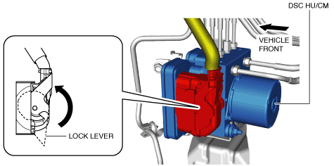
DSC HU/CM Connector Removal Note
-
Caution
-
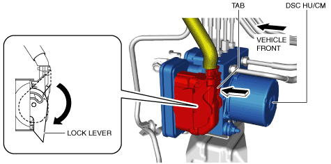
• If sand or other particles get into the connector, it may be difficult to remove. To prevent damaging the connector, be careful not to use excessive force when disconnecting it.
1. Pull the lock lever down in the direction of the arrow while pressing the tab of the lock lever.
2. Disconnect the DSC HU/CM connector.
Brake Pipe Removal Note
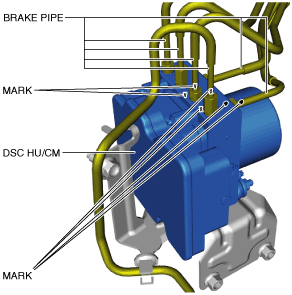
1. Place an alignment mark on the brake pipe and DSC HU/CM.
2. Apply protective tape to the connector to prevent brake fluid from entering.
3. Disconnect the brake pipes.
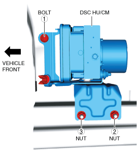
Bolt and Nuts Installation Note
1. Install the bolt and nuts in the order shown in the figure.
-
Tightening torque
-
19—25 N·m {2.0—2.5 kgf·m, 15—18 ft·lbf}
Brake Pipe Installation Note
1. Align the marks made before removal and install the brake pipe to the DSC HU/CM and brake pipe joint referring to the figure.
2. Tighten the brake pipe to the specified torque using the commercially available flare nut wrench.
DSC HU/CM Connector Installation Note
1. Connect the connector and pull the lock lever up in the direction of the arrow.
2. After connecting the connector, verify that the connector cover is completely pushed in.