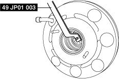
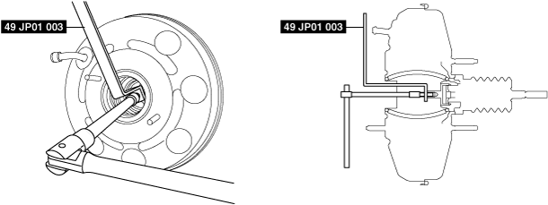
49 JP01 003
Holder

—
—
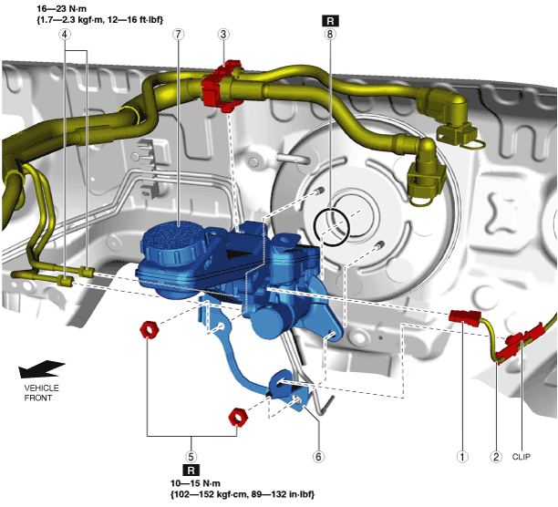
MASTER CYLINDER REMOVAL/INSTALLATION [L.H.D.]
id041100801350
Special Service Tool (SST)
|
49 JP01 003
Holder
|
|
—
|
—
|
||
1. Disconnect the negative battery terminal. (See NEGATIVE BATTERY TERMINAL DISCONNECTION/CONNECTION.)
2. Remove the battery. (See BATTERY REMOVAL/INSTALLATION.)
3. Remove in the order indicated in the table.
4. If the master cylinder is replaced as a single unit, adjust the power brake unit rod. (See Rod Adjustment Note.)
5. Install in the reverse order of removal.
6. After installation, add brake fluid, bleed the air, and inspect for fluid leakage. (See BRAKE FLUID AIR BLEEDING.)
ac9uuw00009549
|
|
1
|
Brake fluid level sensor connector
|
|
2
|
Brake fluid level sensor wiring harness
|
|
3
|
Hose holder
|
|
4
|
Brake pipe
|
|
5
|
Nut
|
|
6
|
Bracket
|
|
7
|
Master cylinder
|
|
8
|
O-ring
|
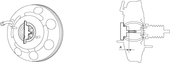
Rod Adjustment Note
1. Install the plate as shown in the figure and verify that the clearance between the rod end and the plate is within the standard.
ac9wzw00004720
|
ac9wzw00004721
|
ac9wzw00004722
|