49 U043 004A
Oil pressure gauge
(Part of 49 U043 0A0A)

49 U043 005
Joint
(Part of 49 U043 0A0A)
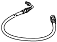
49 U043 006
Hose
(Part of 49 U043 0A0A)
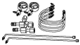
49 U043 0A0A
Oil pressure gauge set
—
—
POWER BRAKE UNIT INSPECTION
id041100801700
Special Service Tool (SST)
|
49 U043 004A
Oil pressure gauge
(Part of 49 U043 0A0A)
|
|
49 U043 005
Joint
(Part of 49 U043 0A0A)
|
|
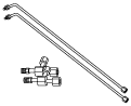
49 U043 006
Hose
(Part of 49 U043 0A0A)
|
|
|
49 U043 0A0A
Oil pressure gauge set
|
|
—
|
—
|
||
Without Using SST
Operation inspection
1. With the engine stopped, pump the pedal a few times.
2. With the pedal depressed, start the engine.
3. If the pedal moves down slightly immediately after starting the engine, the unit is normal.
Vacuum function inspection
1. Start the engine.
2. Stop the engine after driving the vehicle for 1—2 min.
3. Depress the pedal with normal force.
4. If the first pedal stroke is long and becomes shorter with subsequent strokes, the unit is normal.
Vacuum loss function inspection
1. Start the engine.
2. Depress the pedal with normal force.
3. With the pedal depressed, stop the engine.
4. Hold the pedal depressed for approx. 30 s.
5. If the pedal height does not change during this time, the unit is normal.
Using SST
Pre-inspection preparation
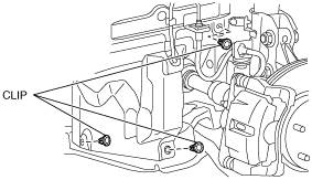
1. Remove the clips.
ac5wzw00000214
|
2. Set the splash shield out of the way.
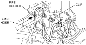
3. Disconnect the brake pipe from the brake hose.
ac5wzw00000215
|
4. Remove the clip.
5. Remove the brake hose from the bracket.
6. Detach the brake pipe from the pipe holder.
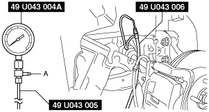
7. Install the SST to the brake pipe as shown in the figure.
ac9uuw00009390
|
8. Bleed the brake line and the SSTs of air. Bleed the air form the SSTs using bleeder screw A.
9. Install the pedal force gauge to the brake pedal.
10. Connect the vacuum gauge to the vacuum line.
Vacuum loss inspection
1. Start the engine.
2. Depress the brake pedal with a force of 200 N {20.4 kgf, 45.0 lbf}.
3. Stop the engine when the vacuum gauge reading reaches 68 kPa {510 mmHg, 20 inHg} with the pedal depressed.
4. With the engine off, observe the vacuum gauge for 15 s.
5. If the gauge has dropped 3.3 kPa {25 mmHg, 1.0 inHg} or less, the unit is normal.
Lack of hydraulic pressure inspection
1. If the pedal force and fluid pressure correlation is within the specification with the engine stopped and a vacuum amount of 0 kPa {0 mmHg, 0 inHg}, the system is normal.
Master cylinder fluid pressure
|
Vacuum amount at 0 kPa {0 mmHg, 0 inHg} |
|
|---|---|
|
Pedal force |
Fluid pressure |
|
200 N {20.4 kgf, 45.0 lbt}
|
610 kPa {6.22 kgf/cm2, 88.5 psi} or more
|
Hydraulic pressure inspection
1. Start the engine. Depress the brake pedal when the vacuum reaches 66.7 kPa {500 mmHg, 19.7 inHg}.
2. At this time, apply the indicated pedal force and if the fluid pressure is within the specification, the unit is normal.
Master cylinder fluid pressure
|
Vacuum amount at 66.7 kPa {500 mmHg, 19.7 inHg} |
|
|---|---|
|
Pedal force |
Fluid pressure |
|
200 N {20.4 kgf, 45.0 lbt}
|
6,350 kPa {64.75 kgf/cm2, 921.0 psi} or more
|
After-inspection procedure
1. After the inspection, remove the SSTs, install the brake hose, clamp, and brake pipe to the original positions, and then bleed the air from the brake line. (See BRAKE HOSE (FRONT) REMOVAL/INSTALLATION.) (See BRAKE FLUID AIR BLEEDING.)