 |
ac9uuw00009552
POWER BRAKE UNIT REMOVAL/INSTALLATION [L.H.D.]
id041100801850
1. Disconnect the negative battery terminal. (See NEGATIVE BATTERY TERMINAL DISCONNECTION/CONNECTION.)
2. Remove the following parts as a single unit. (See INTAKE-AIR SYSTEM REMOVAL/INSTALLATION [SKYACTIV-G 2.5T].)
3. Remove the following parts:
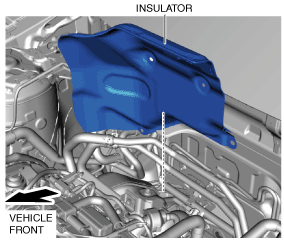
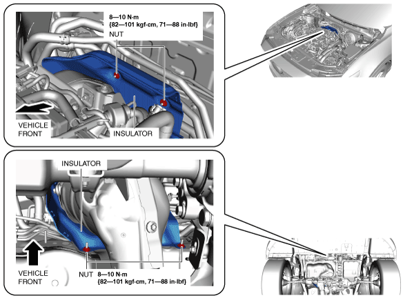
4. Remove the nuts.
ac9uuw00009552
|
5. Remove the insulator.
ac9uuw00008914
|
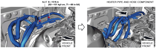
6. Remove the nuts.
7. Set the heater pipe and hose component out of the way as shown in the figure.
ac9uuw00008915
|
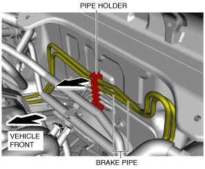
8. Detach the brake pipes from the pipe holder.
ac9uuw00008916
|
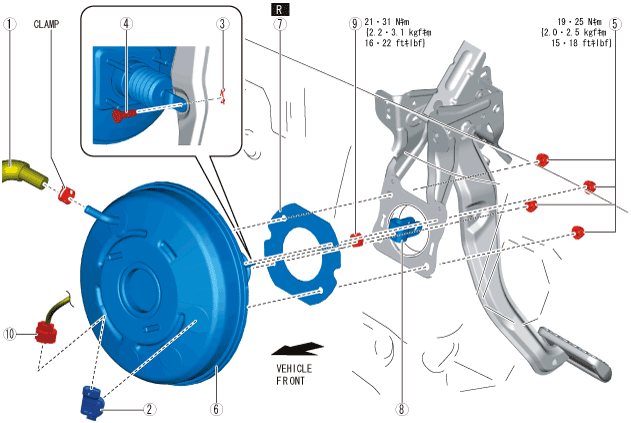
9. Remove in the order indicated in the table.
10. Install in the reverse order of removal.
11. After installation, add brake fluid, bleed the air, and inspect for fluid leakage. (See BRAKE FLUID AIR BLEEDING.)
12. Remove the brake switch. (See BRAKE PEDAL REMOVAL/INSTALLATION [L.H.D.].)
13. Inspect the brake pedal. (See BRAKE PEDAL INSPECTION.)
14. Install a new brake switch. (See BRAKE PEDAL REMOVAL/INSTALLATION [L.H.D.].)
ac9wzw00005728
|
|
1
|
Vacuum hose
|
|
2
|
Power brake unit vacuum sensor connector (vehicles with i-stop)
|
|
3
|
Snap pin
|
|
4
|
Clevis pin
|
|
5
|
Nut
|
|
6
|
Power brake unit
|
|
7
|
Gasket
|
|
8
|
Fork
(See Fork Installation Note.)
|
|
9
|
Nut
|
|
10
|
Power brake unit vacuum sensor (vehicles with i-stop)
|
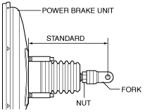
Fork Installation Note
1. Install the fork as shown in the figure.
ac9uuw00009728
|