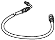
49 U043 004A
Oil pressure gauge
(Part of 49 U043 0A0A)

49 U043 005
Joint
(Part of 49 U043 0A0A)
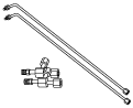
49 U043 006
Hose
(Part of 49 U043 0A0A)
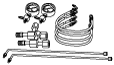
49 U043 0A0A
Oil pressure gauge set
—
—
BRAKE FLUID PRESSURE SENSOR INSPECTION
id041500801500
Special Service Tool (SST)
|
49 U043 004A
Oil pressure gauge
(Part of 49 U043 0A0A)
|
|
49 U043 005
Joint
(Part of 49 U043 0A0A)
|
|
49 U043 006
Hose
(Part of 49 U043 0A0A)
|
|
|
49 U043 0A0A
Oil pressure gauge set
|
|
—
|
—
|
||
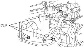
1. Switch the ignition off.
2. Remove the clips.
ac5wzw00000214
|
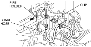
3. Set the splash shield out of the way.
4. Disconnect the brake pipe from the brake hose.
ac5wzw00000215
|
5. Remove the clip.
6. Remove the brake hose from the bracket.
7. Detach the brake pipe from the pipe holder.
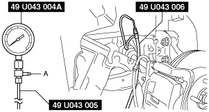
8. Install the SST to the brake pipe as shown in the figure.
ac9uuw00009390
|
9. Bleed the brake line and the SSTs of air. Bleed the air form the SSTs using bleeder screw A.
10. Connect the M-MDS to the DLC-2.
11. Select the “BRK_F_P_R” PID.
12. Start the engine.
13. Depress the brake pedal, and confirm that the fluid pressure value of the SST (Gauge) and the value shown on the M-MDS are equal.
14. After the inspection, remove the SSTs, install the brake hose, clip, and brake pipe to the original positions, and then bleed the air from the brake line. (See BRAKE HOSE (FRONT) REMOVAL/INSTALLATION.) (See BRAKE FLUID AIR BLEEDING.)