MECHANICAL SYSTEM TEST [GW6A-EL, GW6AX-EL]
id0517i2118300
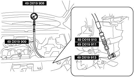
Special Service Tool (SST)
|
49 D019 910
Adapter
(Part of 49 D019 9A2)
|
 |
49 D019 911
Adapter
(Part of 49 D019 9A2)
|
 |
49 D019 913
Adapter
(Part of 49 D019 9A2)
|
 |
|
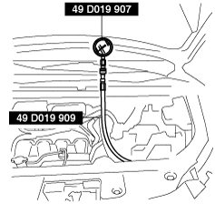
49 D019 909
Hose
(Part of 49 D019 9A2)
|
 |
49 D019 908
Gauge
(Part of 49 D019 9A2)
|
 |
49 D019 907
Oil pressure gauge
(Part of 49 D019 9A2)
|
|
Mechanical System Test Preparation
1. Apply the parking brake firmly, and set the wheel blocks for both the front and rear wheels.
2. Inspect the engine coolant level. (See ENGINE COOLANT LEVEL INSPECTION [SKYACTIV-G 2.5T].)
3. Inspect the engine oil level. (See ENGINE OIL LEVEL INSPECTION [SKYACTIV-G 2.5T].)
4. Inspect the ATF level. (See AUTOMATIC TRANSAXLE FLUID (ATF) INSPECTION [GW6A-EL, GW6AX-EL].)
5. Inspect the ignition timing. (See ENGINE TUNE-UP [SKYACTIV-G 2.5T].)
6. Inspect the idle speed. (See ENGINE TUNE-UP [SKYACTIV-G 2.5T].)
7. Verify that no DTCs are stored.
Line Pressure Test
1. Perform the mechanical system test preparation. (See Mechanical System Test Preparation.)
2. Remove the air cleaner component. (See INTAKE-AIR SYSTEM REMOVAL/INSTALLATION [SKYACTIV-G 2.5T].)
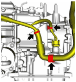
3. Disconnect the wiring harness clip from the harness bracket.
4. Disconnect the oil pipe No.1 from the harness bracket with the oil hose connected. (With oil cooler No.2)
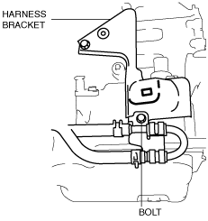
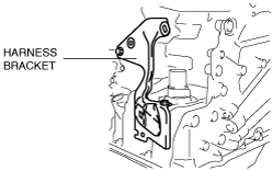
5. Remove the harness bracket.
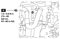
6. Remove the pressure detection square head plug.
-
Warning
-
• Do not remove the square head plug when the ATF temperature is high. Otherwise, ATF could overflow and cause severe burns or serious injury. Remove the square head plug when the transaxle and ATF temperatures are low.
-
Note
-
• Use a suitable oil pressure gauge that corresponds to the line pressure because the maximum scale value differs depending on the oil pressure gauge.
7. Install SSTs (49 D019 908, 49 D019 909, 49 D019 910, 49 D019 911, 49 D019 913) to the line pressure detection port as shown in the figure.
8. Install the air cleaner component. (See INTAKE-AIR SYSTEM REMOVAL/INSTALLATION [SKYACTIV-G 2.5T].)
9. Start the engine.
10. Warm up the engine until the ATF temperature is 60—70 °C {140—158 °F}.
11. Shift the selector lever to the D position.
12. Measure the line pressure while idling in D position.
13. Measure the line pressures while idling in the M (1st gear) and R positions using the same procedure.
14. Stop the engine.
15. Change the low-pressure gauge (49 D019 908) to the high-pressure gauge (49 D019 907).
16. Start the engine.
17. Measure the line pressure while stalling in D position.
- (1) Strongly depress the brake pedal with the left foot.
-
- (2) Shift the selector lever to the D position.
-
-
Caution
-
• To prevent damage to the transaxle, measure the line pressure while stalling (Step (3)—(4)) within 5 s.
- (3) Slowly depress the accelerator pedal fully with the right foot all the way down.
-
- (4) Read the line pressure quickly while stalling, and remove the right foot from the accelerator pedal.
-
- (5) Shift the selector lever to the N position and idle for 1 min or more.
-
18. Measure the line pressure while stalling for positions other than D in the same procedure.
-
• If there is any malfunction, one of the following causes may have occurred:
|
Condition
|
Possible cause
|
|
Lower than specification
|
Lower in R, D, and M (1GR) position
|
• Oil pump wear
• ATF leakage from oil pump, control valve body, and transaxle case
• Pressure regulator valve sticking
• Pressure control solenoid malfunction
• Solenoid reducing valve sticking
|
|
Lower in D and M (1GR) position
|
• ATF leakage from low clutch hydraulic circuit
|
|
Lower in R and M (1GR) position
|
• ATF leakage from low and reverse brake hydraulic circuit
|
|
Lower in R position
|
• ATF leakage from R-3-5 brake hydraulic circuit
|
|
Higher than specification
|
Higher in R, D, and M (1GR) position
|
• Pressure regulator valve sticking
• Pressure control solenoid malfunction
|
Line pressure
|
Measurement conditions
|
Specification (kPa {kgf/cm2, psi})
|
|
Idling
|
R position
|
500—700 {5.10—7.13, 72.6—101.0}
|
|
D and M (1GR) position
|
330—470 {3.37—4.79, 47.9—68.1}
|
|
Stalling
|
R position
|
1,790—2,100 {18.26—21.41, 259.7—304.5}
|
|
D and M (1GR) position
|
970—1,170 {9.90—11.93, 141.0—169.6}
|
19. Stop the engine.
20. Remove the air cleaner component. (See INTAKE-AIR SYSTEM REMOVAL/INSTALLATION [SKYACTIV-G 2.5T].)
21. Remove the SSTs.
-
Warning
-
• If the SST is removed when the ATF temperature is high, ATF could overflow and cause severe burns or serious injury. Remove the SST when the transaxle and ATF temperatures are low.
22. Install a new square head plug.
-
Note
-
• Do not reuse the square head plug because a sealant coating has been applied.
-
Tightening torque
-
7.2—9.8 N·m {74—99 kgf·cm, 64—86 in·lbf}
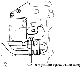
23. Install the harness bracket.
-
Tightening torque
-
8—10 N·m {82—101 kgf·cm, 71—88 in·lbf}
24. Install the oil pipe No.1 to the harness bracket. (With oil cooler No.2)
25. Connect the wiring harness clip to the harness bracket.
26. Install the air cleaner component. (See INTAKE-AIR SYSTEM REMOVAL/INSTALLATION [SKYACTIV-G 2.5T].)
Stall Test
1. Perform the mechanical system test preparation. (See Mechanical System Test Preparation.)
2. Apply the parking brake firmly, and set the wheel blocks for both the front and rear wheels.
3. Start the engine.
4. Measure the stall speed in the D position.
- (1) Strongly depress the brake pedal with the left foot.
-
- (2) Shift the selector lever to the D position.
-
-
Caution
-
• Stall speed: Maximum stall speed during stall test
• If the stall condition is determined in the D or M position, the control for limiting the engine speed is operated to protect the transaxle. Engine speed increases momentarily and decreases gradually during the stall test, however, this does not indicate a malfunction.
• To prevent damage to the transaxle, measure the stall speed (Step (3)—(4)) within 5 s.
- (3) Slowly depress the accelerator pedal fully with the right foot all the way down.
-
- (4) Read the engine speed quickly when the speed is stabilized, and remove the right foot from the accelerator pedal.
-
- (5) Shift the selector lever to the N position and idle for 1 min or more.
-
5. Measure the stall speed in the M (1st gear) and R positions using the same procedure.
-
• If there is any malfunction, one of the following causes may have occurred:
|
Condition
|
Possible cause
|
|
Higher than specification
|
Higher in R, D, and M (1GR) position
|
Line pressure is low
|
• Oil pump wear
• ATF leakage from oil pump, control valve body, and transaxle case
• Pressure regulator valve sticking
• TR control valve sticking
• Pressure control solenoid operation malfunction
|
|
• Low and reverse brake slippage, and damage of one-way clutch
|
|
Higher in D and M (1GR) position
|
• Low clutch slippage
• One-way clutch damage
|
|
Higher in R position
|
Perform road test to determine whether problem is in R-3-5 brake or low and reverse brake
• Engine brake operates in M (1GR) position
-
? R-3-5 brake slippage
• Engine braking does not operate in M (1GR) position
-
? Low and reverse brake slippage
|
|
Lower than specification
|
Lower in R, D, and M (1GR) position
|
• Engine malfunction
• One-way clutch slippage in torque converter
|
Stall speed
|
Measurement conditions
|
Standard value (rpm)
|
|
R position
|
1,800—2,400
|
|
D position
|
2,200—3,100
|
|
M position
|
Time Lag Test
1. Perform the mechanical system test preparation. (See Mechanical System Test Preparation.)
2. Apply the parking brake firmly, and set the wheel blocks for both the front and rear wheels.
3. Start the engine.
4. Measure the time lag from the N position to the D position.
- (1) Shift the selector lever from the N position to the D position with the brake pedal depressed.
-
- (2) Measure the time until the shift shock is felt firmly after shifting.
-
5. Measure the time lag from the N position to the R position using the same procedure.
-
• If there is any malfunction, one of the following causes may have occurred:
|
Condition
|
Possible cause
|
|
N to D selected
|
Longer than specification
|
• Line pressure is low
• Low clutch slippage
• ATF leakage from low clutch hydraulic circuit
• ATF leakage from low and reverse brake hydraulic circuit
• Shift solenoid No.1 operation malfunction
• Shift solenoid No.4 operation malfunction
|
|
Shorter than specification
|
• Line pressure is high
• N-D accumulator operation malfunction
• Shift solenoid No.1 operation malfunction
• Shift solenoid No.4 operation malfunction
|
|
N to R selected
|
Longer than specification
|
• Line pressure is low
• Low and Reverse brake slippage
• R-3-5 brake slippage
• ATF leakage from R-3-5 brake hydraulic circuit
• ATF leakage from low and reverse brake hydraulic circuit
• Shift solenoid No.3 operation malfunction
• Shift solenoid No.4 operation malfunction
|
|
Shorter than specification
|
• Line pressure is high
• N-R accumulator operation malfunction
• Shift solenoid No.3 operation malfunction
• Shift solenoid No.4 operation malfunction
|
Time lag
|
Measurement conditions
|
Specification (s)
|
|
N to D selected
|
0.4—0.7
|
|
N to R selected
|