 |
ac9wzw00006523
INTAKE-AIR SYSTEM REMOVAL/INSTALLATION [SKYACTIV-G 2.5T]
id0113q4801900
1. Disconnect the negative battery terminal. (See NEGATIVE BATTERY TERMINAL DISCONNECTION/CONNECTION.)
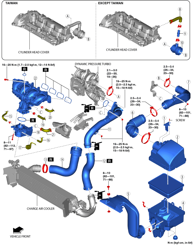
2. Remove in the order indicated in the table.
3. Install in the reverse order of removal.
ac9wzw00006523
|
|
1
|
MAF sensor/IAT sensor No.1
|
|
2
|
Air cleaner cover
|
|
3
|
Air cleaner element
|
|
4
|
Air cleaner case
|
|
5
|
Fresh-air duct
(See Fresh-air Duct Removal Note.)
|
|
6
|
Air hose
|
|
7
|
Air inlet pipe
(See Air Inlet Pipe Removal Note.)
|
|
8
|
Breather hose
|
|
9
|
Ventilation pipe
|
|
10
|
Turbocharger air inlet hose
|
|
11
|
Turbocharger air outlet pipe
|
|
12
|
Charge air cooler inlet hose
|
|
13
|
Hose clamp
(See Hose Clamp Installation Note.)
|
|
14
|
Charge air cooler outlet hose
|
|
15
|
Water hose No.2
|
|
16
|
Water hose No.1
|
|
17
|
Throttle body connector
|
|
18
|
Throttle body
|
|
19
|
Vacuum hose No.2
|
|
20
|
Vacuum hose No.1
|
|
21
|
PCV hose
|
|
22
|
Intake manifold
|
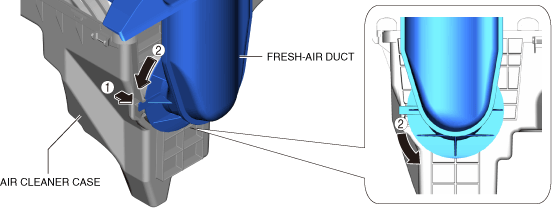
Fresh-air Duct Removal Note
1. While moving the tabs in the direction shown in the figure, rotate the fresh-air duct.
ac9uuw00009326
|
2. Remove the fresh-air duct.
Air Inlet Pipe Removal Note
1. Remove the battery. (See BATTERY REMOVAL/INSTALLATION.)
2. Remove the air inlet pipe.
Turbocharger Air Outlet Pipe Removal Note
1. Remove the battery tray. (See BATTERY REMOVAL/INSTALLATION.)
2. Remove the turbocharger air outlet pipe.
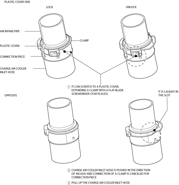
Charge Air Cooler Inlet Hose Removal Note
1. Remove the front under cover No.1. (See FRONT UNDER COVER No.1 REMOVAL/INSTALLATION.)
2. Remove the front under cover No.2. (See FRONT UNDER COVER No.2 REMOVAL/INSTALLATION.)
3. Release the lock and remove the charge air cooler inlet hose as shown in the figure.
ac9uuw00009375
|
Charge Air Cooler Outlet Hose Removal Note
1. Release the lock of connector and remove the charge air cooler outlet hose.
ac9uuw00009376
|
Intake Manifold Removal Note
1. Drain the engine coolant. (See ENGINE COOLANT REPLACEMENT [SKYACTIV-G 2.5T].)
2. Remove the plug hole plate. (See PLUG HOLE PLATE REMOVAL/INSTALLATION [SKYACTIV-G 2.5T].)
3. Remove the EGR cooler. (See EGR COOLER REMOVAL/INSTALLATION [SKYACTIV-G 2.5T].)
4. Remove the EGR pipe. (See EGR PIPE REMOVAL/INSTALLATION [SKYACTIV-G 2.5T].)
5. Remove the MAP sensor/IAT sensor No.2. (See MANIFOLD ABSOLUTE PRESSURE (MAP) SENSOR/INTAKE AIR TEMPERATURE (IAT) SENSOR NO.2 REMOVAL/INSTALLATION [SKYACTIV-G 2.5T].)
6. Disconnect the water hose from the water outlet component.
7. Disconnect the high fuel pressure sensor connector. (See FUEL INJECTOR REMOVAL/INSTALLATION [SKYACTIV-G 2.5T].)
8. Disconnect the wiring harness clips from the intake manifold.
9. Remove the intake manifold.
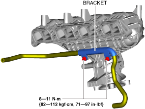
10. Remove the bracket from the intake manifold.
ac9uuw00009697
|
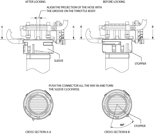
Charge Air Cooler Outlet Hose Installation Note
1. Install the charge air cooler outlet hose as shown in the figure.
ac9uuw00009698
|
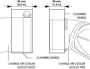
Hose Clamp Installation Note
1. Visually inspect the charge air cooler outlet hose and charge air cooler outlet pipe.
2. Use a clean cloth to clean the outer surfaces of the charge air cooler outlet pipe and the charge air cooler outlet hose.
ac9uuw00009377
|
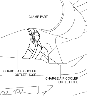
3. Temporarily install a new hose clamp to the charge air cooler outlet hose. (Do not tighten hose clamp)
ac5wzw00007965
|
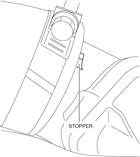
4. Insert the charge air cooler outlet hose until it contacts the charge air cooler outlet pipe stopper.
ac5wzw00007966
|
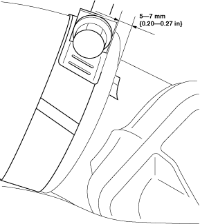
5. Re-position the temporarily installed hose clamp to the position 5—7 mm {0.20—0.27 in} from the charge air cooler outlet pipe stopper.
ac5wzw00007967
|
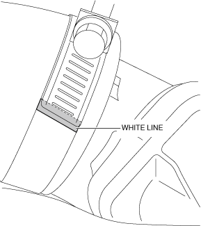
6. Tighten the hose clamp until the clamp end rides on top of the white line.
ac5wzw00007968
|
Charge Air Cooler Inlet Hose Installation Note
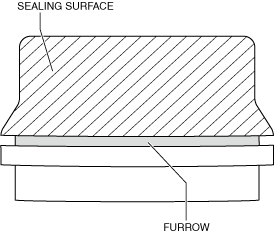
1. Clean the seal surface and furrow area of the charge air cooler air inlet pipe and turbocharger air outlet pipe.
ac5wzw00006724
|
2. Degrease the seal surface of the pipe, and verify if there is foreign matter penetration or scratches.
3. Apply engine oil to the seal surface of the pipe.
ac9uuw00009378
|
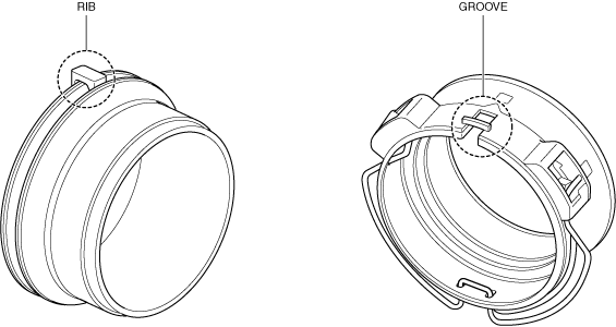
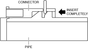
4. Align the pipe rib and connector groove positions, and install.
ac5wzw00006726
|
5. Insert the pipe connector completely into the connector.
ac5wzw00006727
|
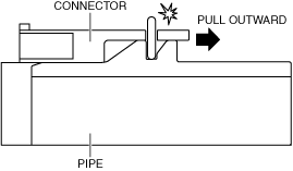
6. Pull the pipe outward and verify that a click sound is heard.
ac5wzw00006728
|
7. Install the front under cover No.2. (See FRONT UNDER COVER No.2 REMOVAL/INSTALLATION.)
8. Install the front under cover No.1. (See FRONT UNDER COVER No.1 REMOVAL/INSTALLATION.)