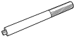
49 G030 796
Body
(Part of 49 G030 795)

49 F027 003
Handle
49 U034 204
Dust boot installer

OIL SEAL (CONTROL VALVE BODY) REPLACEMENT [GW6A-EL, GW6AX-EL]
id0517i2118700
Special Service Tool (SST)
|
49 G030 796
Body
(Part of 49 G030 795)
|
|
49 F027 003
Handle
|
|
49 U034 204
Dust boot installer
|
|
1. Disconnect the negative battery terminal. (See NEGATIVE BATTERY TERMINAL DISCONNECTION/CONNECTION.)
2. Remove the air cleaner component. (See INTAKE-AIR SYSTEM REMOVAL/INSTALLATION [SKYACTIV-G 2.5T].)
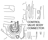
3. Disconnect the control valve body connector.
ac5wzw00003968
|
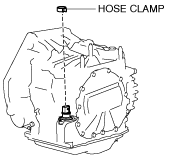
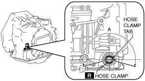
4. Remove the hose clamp.
ac5wzw00003969
|
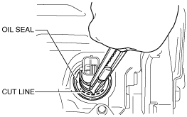
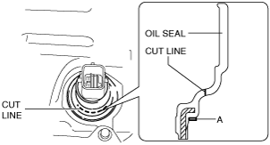
5. Cut the oil seal using a utility knife as shown in the following illustration.
ac5wzw00004562
|
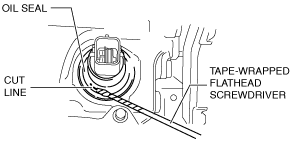
6. Using a tape-wrapped flathead screwdriver, remove the oil seal from the transaxle case.
ac5wzw00004563
|
ac5wzw00004564
|
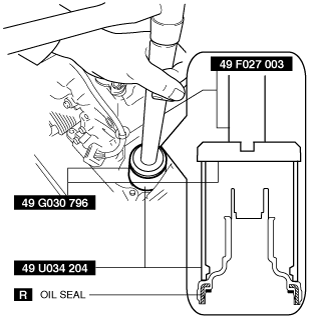
7. Temporarily install the oil seal (control valve body) by hand.
8. Using the SSTs and a hammer, install the oil seal (control valve body) so that it is not tilted and there is no height difference between the transaxle case surface and the end surface of the oil seal.
ac5wzw00003749
|
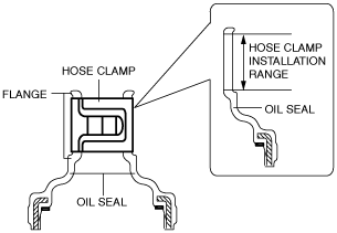
9. Install a new hose clamp to the position shown in the figure.
ac5wzw00003970
|
am3zzw00012679
|
10. Connect the control valve body connector.
ac5wzw00003968
|
11. Install the air cleaner component. (See INTAKE-AIR SYSTEM REMOVAL/INSTALLATION [SKYACTIV-G 2.5T].)
12. Connect the negative battery terminal. (See NEGATIVE BATTERY TERMINAL DISCONNECTION/CONNECTION.)