49 B032 317
Bearing & oil seal remover

49 T028 301
Dust boot installer

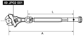
49 JP02 001
Adjustable wrench

49 T025 001
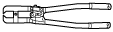
Boot clamp crimpers
—
—
STEERING GEAR AND LINKAGE ASSEMBLY
id061300802100
Special Service Tool (SST)
|
49 B032 317
Bearing & oil seal remover
|
|
49 T028 301
Dust boot installer
|
|
49 JP02 001
Adjustable wrench
|
|
|
49 T025 001
Boot clamp crimpers
|
|
—
|
—
|
||
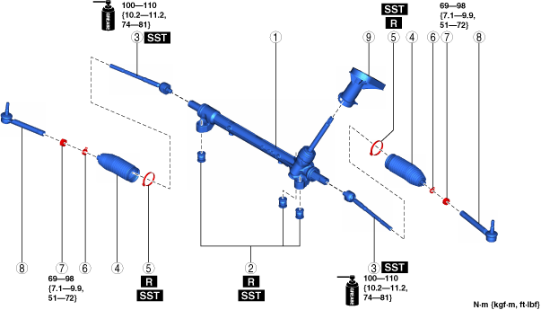
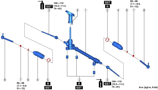
1. Assemble in the order shown in the figure.
2. Install the steering gear and linkage. (See STEERING GEAR AND LINKAGE REMOVAL/INSTALLATION.)
L.H.D.
ac9wzw00005267
|
R.H.D.
ac9wzw00003546
|
|
1
|
Steering gear
|
|
2
|
Mounting rubber
|
|
3
|
Tie Rod
(See Tie Rod Assembly Note.)
|
|
4
|
Boot
|
|
5
|
Boot band
(See Boot Band Assembly Note.)
|
|
6
|
Boot clamp
|
|
7
|
Locknut
|
|
8
|
Tie-rod end
(See Tie-rod End Assembly Note.)
|
|
9
|
Dust cover
|
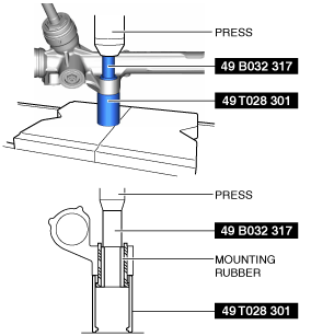
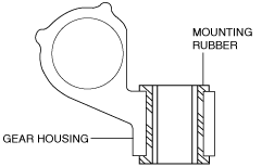
Mounting Rubber Assembly Note
1. Apply soapy water to the rubber part of the mounting rubber.
2. Press fit the ear portion of the mounting rubber (lower side) using the SSTs until it projects from the gear housing as shown in the figure.
ac9uuw00006226
|
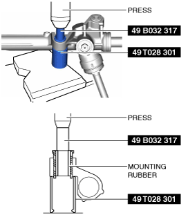
3. Reverse the gear housing, then press fit the mounting rubber using the SSTs and the press until the mounting rubber ear portion (upper side) contacts the gear housing.
ac9uuw00006227
|
4. Verify that both mounting rubber ears are correctly assembled with no gaps between them and the gear housing as shown in the figure.
ac9uuw00006228
|
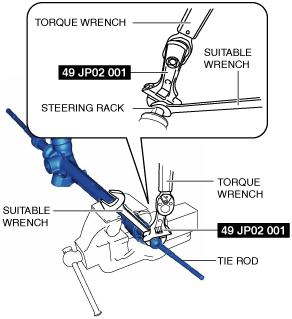
Tie Rod Assembly Note
1. Install the SST to the torque wrench as shown in the figure, set it on the tie rod, and measure dimensions A and L shown in the figure.
adejjw00015170
|
2. Tighten the tie rod after calculating the tightening torque using the following formula.
ac9uuw00006229
|
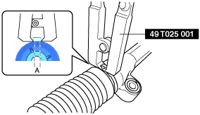
Boot Band Assembly Note
1. Assemble the boot band to the boot.
2. Crimp the boot band using the SST.
ac9uuw00006230
|
3. Verify that the crimping clearance A is within the specification.
4. Rotate the by hand and verify that it is securely installed to the boot band.
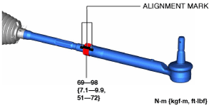
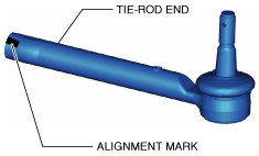
Tie-rod End Assembly Note
1. Align the marks that were made before removing the tie-rod end, and assemble the tie-rod end to the tie rod.
ac9uuw00006231
|
ac9uuw00006232
|
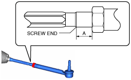
2. Verify that dimension A shown in the figure is within the specification.
ac9uuw00006233
|