 |
ac9uuw00006217
STEERING GEAR AND LINKAGE REMOVAL/INSTALLATION
id061300801700
1. Remove the wheels and tires. (See WHEEL AND TIRE REMOVAL/INSTALLATION.)
2. Remove the joint cover. (See STEERING WHEEL AND COLUMN REMOVAL/INSTALLATION.)
3. Disconnect the intermediate shaft from the steering gear and linkage. (See STEERING WHEEL AND COLUMN REMOVAL/INSTALLATION.)
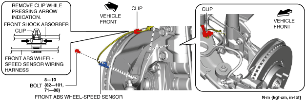
4. Disconnect the front ABS wheel-speed sensor wiring harness installed to the steering knuckle and set it aside. (See FRONT ABS WHEEL-SPEED SENSOR REMOVAL/INSTALLATION.)
ac9uuw00006217
|
5. Remove the front under cover No.2. (See FRONT UNDER COVER No.2 REMOVAL/INSTALLATION.)
6. Remove the front under cover No.1. (See FRONT UNDER COVER No.1 REMOVAL/INSTALLATION.)
7. Remove the front splash shield. (See FRONT SPLASH SHIELD REMOVAL/INSTALLATION.)
8. Remove the front crossmember component. (See FRONT CROSSMEMBER REMOVAL/INSTALLATION.)
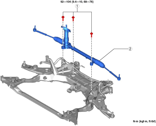
9. Remove in the order indicated in the table.
10. Install in the reverse order of removal.
L.H.D.
ac9wzw00005079
|
R.H.D.
ac9wzw00003311
|
|
1
|
Steering gear and linkage installation bolt
|
|
2
|
Steering gear and linkage
|
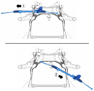
Steering Gear and Linkage Removal Note
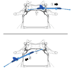
1. Remove the steering gear and linkage installation bolts, move the steering gear and linkage in the direction and order of the arrows shown in the figure, and then remove it.
L.H.D.
ac9uuw00006219
|
R.H.D.
ac9wzw00003312
|
Steering Gear and Linkage Installation Bolt Installation Note
1. Temporarily tighten the bolts.
2. Tighten the bolts to the specified torque.