|
ac9uuw00005360
REFRIGERANT CHARGING
id071000300100
Charging Recycled Refrigerant
1. Correctly collect the refrigerant following the instructions for the chlorofluorocarbon (CFC) recovery machine being used.
Adding Compressor Oil
1. Weigh the compressor oil which is exhausted when collecting the refrigerant.
2. When adding refrigerant, add new compressor oil equivalent in weight to the exhausted amount to the refrigerant cycle.
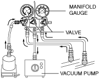
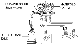
Charging Preparation
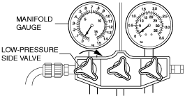
1. Close all the valves of the manifold gauge.
ac9uuw00005360
|
2. Close the refrigerant tank valve.
3. Install the manifold gauge set. (See MANIFOLD GAUGE SET CONNECTION.)
4. Connect the vacuum pump hose to the manifold gauge.
5. Connect the tap pin side of the charging hose to the air purge valve of the manifold gauge.
6. Connect the charging hose to the refrigerant tank (no-tap pin side).
7. Place the refrigerant tank on the scale.
8. Connect the vacuum pump hose to the vacuum pump.
9. Perform a evacuation. (See Evacuation.)
Evacuation
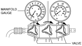
1. Open all the valves of the manifold gauge.
ac9uuw00005361
|
2. Start the vacuum pump and let it operate for 15 min.
3. Verify that high- and low-pressure side readings of the manifold gauge are at -0.1 MPa {-1 kgf/cm2, -15 psi}.
4. Stop the vacuum pump.
5. Close all the valves of the manifold gauge.
ac9uuw00005362
|
6. Wait for 5 min after stopping the vacuum pump, and perform an airtightness check for the refrigerant system. (See Airtightness Check.)
Airtightness Check
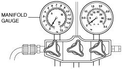
1. Verify that the manifold gauge reading has not changed.
ac9uuw00005363
|
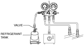
Charging New Refrigerant
1. Open the valve of the refrigerant tank.
ac9uuw00005364
|
2. Weigh the refrigerant tank to charge the suitable amount of refrigerant.
3. Open the low-pressure side valve of the manifold gauge.
ac9uuw00005365
|
4. Verify that low-pressure side readings of the manifold gauge is at 0.1 MPa {1 kgf/cm2, 15 psi}.
5. Close the low-pressure side valve of the manifold gauge.
ac9uuw00005366
|
6. Inspect for gas leakage from the piping connection using a gas leak detector or a fluorescent agent-detecting UV black light.
7. Inspect for leakage again.
8. Open the low-pressure side valve of the manifold gauge.
ac9uuw00005365
|
9. Charge with refrigerant until the weight of refrigerant tank has decreased 250 g {8.82 oz} from the amount in Step 2.
10. Close the low-pressure side valve of the manifold gauge.
ac9uuw00005366
|
11. Start the engine and actuate the A/C compressor.
12. Open the low-pressure side valve of the manifold gauge and charge with refrigerant until the weight of the refrigerant tank has decreased regular amount from the amount in Step 2.
ac9uuw00005365
|
13. Close the low-pressure side valve of the manifold gauge.
ac9uuw00005366
|
14. Stop the engine.
15. Perform the leak test. (See Leak Test.)
Leak Test
1. Inspect for gas leakage from the piping connection using a gas leak detector or a fluorescent agent-detecting UV black light.
2. Inspect for leakage again.
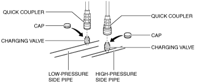
3. Disconnect the quick couplers from the charging valves.
ac9uuw00007480
|
4. Install the caps to the charging valves.