 |
ac9uuw00007519
MAGNETIC CLUTCH DISASSEMBLY/ASSEMBLY
id071100006300
Magnetic Clutch is Disassembled/Assembled with A/C Compressor Removed from Vehicle
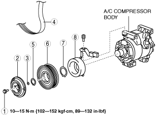
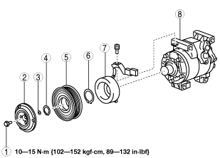
1. Disassemble in the order indicated in the table.
ac9uuw00007519
|
|
1
|
Bolt
|
|
2
|
Pressure plate
|
|
3
|
Shim
|
|
4
|
Snap ring
|
|
5
|
A/C compressor pulley
|
|
6
|
Snap ring
|
|
7
|
Stator
|
|
8
|
A/C compressor body
|
2. Assemble in the reverse order of disassembly.
3. Adjust the magnetic clutch clearance. (See MAGNETIC CLUTCH ADJUSTMENT.)
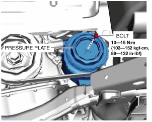
Bolt removal/installation note
1. When removing or installing the bolt, lock the A/C compressor pulley against rotation using the following procedure.
ac5wzw00001840
|
ac5wzw00001841
|
2. When installing a new A/C compressor body, replace the recommended bolt.
Magnetic Clutch is Disassembled/Assembled with A/C Compressor Equipped to Vehicle
1. Remove the following parts:
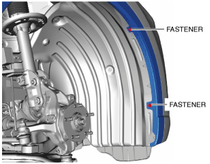
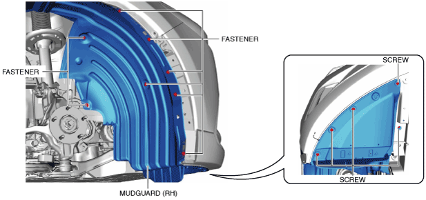
2. Remove the fasteners.
ac9uuw00007520
|
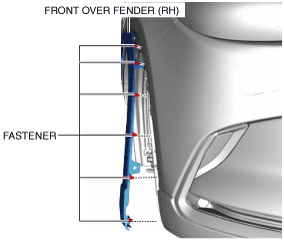
3. Remove the fasteners.
ac9uuw00007521
|
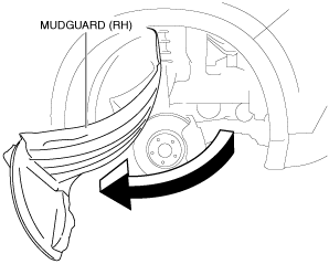
4. Bend back the front side of the front over fender (RH) as shown in the figure.
5. Remove the fasteners.
ac9uuw00007522
|
6. Remove the screws.
7. Bend back the front side of the mudguard (RH) as shown in the figure.
ac9uuw00007523
|
8. Disassemble in the order indicated in the table.
ac9uuw00007524
|
|
1
|
Bolt
|
|
2
|
Pressure plate
|
|
3
|
Shim
|
|
4
|
Drive belt
|
|
5
|
Snap ring
|
|
6
|
A/C compressor pulley
|
|
7
|
Snap ring
|
|
8
|
Stator
|
9. Assemble in the reverse order of disassembly.
10. Adjust the magnetic clutch clearance. (See MAGNETIC CLUTCH ADJUSTMENT.)
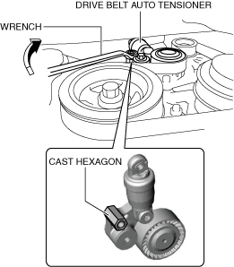
Bolt removal/installation note
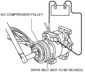
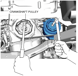
1. When removing or installing the bolt, lock the A/C compressor pulley against rotation using the following procedure.
2. Secure the crankshaft pulley.
ac9uuw00007525
|
3. Remove the bolt with the pressure plate secured.
ac9uuw00007526
|
ac9uuw00007527
|
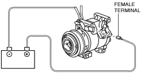
4. Turn the A/C relay off using the “ACCS” simulation function.
Stator removal/installation note
1. Disconnect the negative battery terminal. (See NEGATIVE BATTERY TERMINAL DISCONNECTION/CONNECTION.)
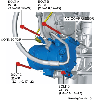
2. Disconnect the magnetic clutch connector.
ac9uuw00007528
|
3. Remove the bolts A, B and C.
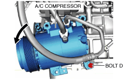
4. Loose bolt D approx. 5 mm {0.2 in}.
5. Tilt the A/C compressor centered around bolt D.
ac9uuw00007529
|
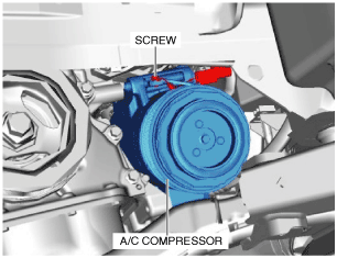
6. Remove the screw.
ac9uuw00007530
|