|
1
|
DETERMINE IF MALFUNCTION CAUSE IS DOOR LOCK
• Refer to “door lock does not operate” malfunction diagnosis and perform the inspection.
• Is the lock/unlock operation performed using the remote transmitter?
|
Yes
|
Troubleshooting completed. (Explain the contents of the servicing to the customer.)
|
|
No
|
Go to the next step.
|
|
2
|
INSPECT ROOM FUSE CONDITION
• Is the fuse (ROOM fuse) normal?
|
Yes
|
Go to the next step.
|
|
No
|
• If the fuse installation is poor:
-
? Install the ROOM fuse properly.
• If the fuse is blown:
-
? Refer to the wiring diagram and verify whether or not there is a common connector between fuse and LF control unit terminal B.
If there is a common connector:
-
• Determine the malfunctioning part by inspecting the common connector and the terminal for corrosion, damage, or pin disconnection, and the common wiring harness for a short to ground.
• Repair or replace the malfunctioning part.
If there is no common connector:
-
• Repair or replace the wiring harness which has a short to ground.
• Replace the fuse.
• If the fuse is damaged:
-
? Replace the fuse.
Go to Step 15.
|
|
3
|
INSPECT REMOTE TRANSMITTER BATTERY POWER
• Inspect the battery power of the remote transmitter.
• Does the KEY indicator light (green) flash for approx. 30 s?
|
Yes
|
-
Note
-
• If the KEY indicator light (green) flashes for approx. 30 s, the battery power of the remote transmitter is low.
Replace the remote transmitter battery and go to Step 15.
|
|
No
|
Go to the next step.
|
|
4
|
REGISTER REMOTE TRANSMITTER
• Register the remote transmitter.
• Clear the DTC for the start stop unit using the M-MDS.
• Retrieve the start stop unit DTCs using the M-MDS.
• Is the lock/unlock operation performed using the remote transmitter?
|
Yes
|
Go to Step 15.
|
|
No
|
Go to the next step.
|
|
5
|
VERIFY IF MALFUNCTION CAUSE IS EXTERNAL NOISE
• Ask the customer malfunction condition.
• Does the malfunction occur at the specified place where external noise is received such as a TV tower, electric power station, or a broadcast station?
|
Yes
|
System is normal. (Explain the customer that operation cannot be performed caused by external noise.)
|
|
No
|
Go to the next step.
|
|
6
|
VERIFY IF MALFUNCTION CAUSE IS OPERATION OTHER THAN OPERATION PERMISSION CONDITION
• Did the customer operate the remote transmitter with all the following conditions met?
-
? All doors and liftgate are closed.
? Ignition switched off (LOCK)
|
Yes
|
Go to the next step.
|
|
No
|
System is normal. (Explain the customer operation condition.)
|
|
7
|
DETERMINE IF MALFUNCTION CAUSE IS NON-STANDARD EQUIPMENT
• Did the malfunction occur after installing the following non-standard equipment?
-
? Mobile telephone or radio set
? Part with built-in micro computer
? Remote engine starter
? TV
|
Yes
|
Go to the next step.
|
|
No
|
Go to Step 9.
|
|
8
|
DETERMINE IF MALFUNCTION CAUSE IS NON-STANDARD EQUIPMENT
• Disconnect the connector for non-standard equipment.
• Perform the lock/unlock operation using the remote transmitter.
• Does it operate normally?
|
Yes
|
System is normal. (Explain to the customer that noise from the non-standard equipment affected the operation.)
|
|
No
|
Go to the next step.
|
|
9
|
VERIFY REMOTE TRANSMITTER BATTERY CONDITION
• Visually inspect the remote transmitter battery for the following:
-
? Method of battery insertion (polarity)
? Battery type (CR2025)
? Corrosion, soiling, deformation of battery terminals (plus/minus terminals).
? Contact malfunction between the battery terminal and battery when battery is inserted
• Is there any malfunction?
|
Yes
|
Battery insertion direction, battery type is incorrect:
• Properly install the battery or replace the battery with a specified one (CR2025), then go to the next step.
Battery terminal malfunction:
• Clean corrosion and soiling, or repair or replace the terminal, then go to the next step.
|
|
No
|
Go to Step 11.
|
|
10
|
VERIFY REMOTE TRANSMITTER OPERATION
• Perform the lock/unlock operation using the remote transmitter.
• Is the lock/unlock operation performed normally?
|
Yes
|
Troubleshooting completed.
|
|
No
|
Go to the next step.
|
|
11
|
DETERMINE IF MALFUNCTION CAUSE IS REMOTE TRANSMITTER
-
Note
-
• For a monitor battery, use a new battery or one which operates normally on another vehicle.
• Replace the battery in all the remote transmitters with a monitor-use battery.
• For each remote transmitter, verify that the remote transmitter operation indicator light (LED) illuminates when a button is operated.
• Does operation indicator light (LED) for each remote transmitter operate?
|
Yes
|
Go to the next step.
|
|
No
|
If the operation indicator light (LED) does not illuminate, replace the remote transmitter, then go to the Step 15.
|
|
12
|
DETERMINE IF MALFUNCTION CAUSE IS BATTERY
-
Note
-
• Inspect for all remote transmitters.
• Inspect while the batteries for all of the remote transmitters are replaced with monitor-use batteries.
• Perform the lock/unlock operation using all the remote transmitters.
• Is the lock/unlock operation performed normally?
|
Yes
|
Replace the battery, then go to Step 15.
|
|
No
|
Go to the next step.
|
|
13
|
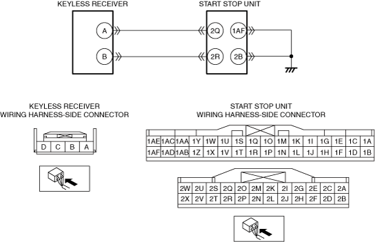
INSPECT IF MALFUNCTION CAUSE IS OPEN CIRCUIT IN WIRING HARNESS BETWEEN START STOP UNIT AND GROUND
• Verify that the start stop unit connector is disconnected.
• Inspect for continuity between the following terminals (vehicle wiring harness).
-
? Start stop unit terminal 1AF and ground
? Start stop unit terminal 2B and ground
• Is there continuity?
|
Yes
|
Go to the next step.
|
|
No
|
• Repair or replace the wiring harness for an open circuit.
• After repair, go to Step 15.
|
|
14
|
INSPECT IF MALFUNCTION CAUSE IS OPEN CIRCUIT IN WIRING HARNESS BETWEEN KEYLESS RECEIVER AND START STOP UNIT OR KEYLESS RECEIVER
• Disconnect the negative battery terminal.
• Disconnect the keyless receiver and start stop unit connector.
• Inspect for continuity between the following terminals (vehicle wiring harness).
-
? Keyless receiver terminal A and start stop unit terminal 2Q
? Keyless receiver terminal B and start stop unit terminal 2R
• Is there continuity?
|
Yes
|
• Inspect the keyless receiver. If there is any malfunction, replace it.
• After repair, go to the next step.
|
|
No
|
• Repair or replace the wiring harness for an open circuit.
• After repair, go to the next step.
|
|
15
|
VERIFY IF MALFUNCTION CAUSE WAS CORRECTED
• Perform the lock/unlock operation using all the remote transmitters.
• Is the lock/unlock operation performed normally?
|
Yes
|
Troubleshooting completed. (Explain the contents of the servicing to the customer.)
|
|
No
|
If the malfunction has not been resolved, repeat the inspection from Step 1.
|