|
1
|
VERIFY IF MALFUNCTION DUE TO LANGUAGE SETTING OF CONNECTIVITY MASTER UNIT (CMU)
• Switch the ignition to ACC or ON (engine off or on).
• Select the following by operating the commander switch or the center display.
-
? Settings
? System
? Language
• Does the language set to the CMU match the language used in voice operations?
|
Yes
|
Go to the next step.
|
|
No
|
Select the language used for voice operations, then go to Step 12.
|
|
2
|
VERIFY IF MALFUNCTION DUE TO CUSTOMER USE METHOD
• Switch the ignition to ACC or ON (engine off or on).
• Press the TALK button on the steering switch.
• After the voice guidance instructs the user to speak after the beep, say, “AM” into the microphone in a normal or slightly loud voice.
• Does the center display change to the AM radio screen?
Determination criteria
-
? Screen changes to AM screen once or more by voicing 10 times.
|
Yes
|
System is normal. (Explain the contents of the servicing to the customer)
|
|
No
|
Go to the next step.
|
|
3
|
VERIFY IF MALFUNCTION DUE TO EFFECTS OF SURROUNDING ENVIRONMENT
• Verify if air from the A/C is being blown against the microphone.
• Move the vehicle to a location with little external noise.
• Press the TALK button on the steering switch.
• After the voice guidance instructs the user to speak after the beep, say, “AM” into the microphone in a normal or slightly loud voice.
• Does the center display change to the AM radio screen?
Determination criteria
-
? Screen changes to AM screen once or more by voicing 10 times.
|
Yes
|
System is normal. (Explain the contents of the servicing to the customer)
|
|
No
|
Go to the next step.
|
|
4
|
DETERMINE IF MALFUNCTION IS SPEAKER, AUDIO AMPLIFIER RELATED
• Switch the ignition to ACC or ON (engine off or on).
• Launch the on-board diagnostic assist function.
• Select assist code “94”.
• Press the [ENTER] and verify that the sound is output from each speaker.
• Is sound output from each speaker?
|
Yes
|
The speakers and audio amplifier are normal.
Go to the next step.
|
|
No
|
Perform malfunction diagnosis according to NO SOUND OUTPUT IN ALL MODES.
|
|
5
|
DETERMINE IF MALFUNCTION IS TAU
• Switch the ignition to ACC or ON (engine off or on).
• Operate the command switch or center display and verify if sound is output from the following modes.
-
? Bluetooth® audio
? Internet radio
? USB audio
• Is sound output?
|
Yes
|
TAU is normal. Go to the next step.
|
|
No
|
Perform malfunction diagnosis according to NO SOUND OUTPUT IN MULTIPLE MODES.
|
|
6
|
DETERMINE IF MALFUNCTION IS MICROPHONE RELATED
• Switch the ignition to ACC or ON (engine off or on).
• Launch the on-board diagnostic assist function.
• Select assist code “61”.
• Press ENTER.
• Say, “AM” into the microphone in a normal or slightly loud voice.
• When speaking, verify if the “Microphone” item is displayed.
• Is the “Microphone” item displayed?
|
Yes
|
The microphone is normal. Go to Step 11.
|
|
No
|
Go to the next step.
|
|
7
|
MICROPHONE CONNECTOR INSPECTION
• Switch the ignition off.
• Disconnect the negative battery terminal.
• Disconnect the microphone connector.
• Inspect the connector engagement and connection condition and inspect the terminals for damage, deformation, corrosion, or disconnection.
• Is the connector normal?
|
Yes
|
Go to the next step.
|
|
No
|
Repair or replace the connector, then go to Step 12.
|
|
8
|
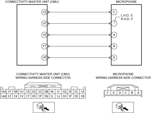
VERIFY IF MALFUNCTION CAUSE IS OPEN CIRCUIT IN WIRING HARNESS BETWEEN CMU AND MICROPHONE
• Switch the ignition off.
• Disconnect the CMU connector.
• Verify that the microphone connector is disconnected.
• Inspect the wiring harness for continuity between the following terminals (vehicle wiring harness side).
-
? CMU terminal 1P and microphone terminal E (L.H.D.)/F (R.H.D.)
? CMU terminal 1R and microphone terminal D
? CMU terminal 1S and microphone terminal A
? CMU terminal 1T and microphone terminal B
• Is there continuity?
|
Yes
|
Go to the next step.
|
|
No
|
• Refer to the wiring diagram and verify if there is a common connector between the following terminals.
-
? CMU terminal 1P and microphone terminal E (L.H.D.)/F (R.H.D.)
? CMU terminal 1R and microphone terminal D
? CMU terminal 1S and microphone terminal A
? CMU terminal 1T and microphone terminal B
If there is a common connector:
-
• Inspect the common connector and terminals for corrosion, damage, or disconnection and the common wiring harnesses for an open circuit to determine the malfunctioning location.
• Repair or replace the malfunctioning location.
If there is no common connector:
-
• Repair or replace the wiring harness which has an open circuit.
• Go to Step 12.
|
|
9
|
VERIFY IF MALFUNCTION CAUSE IS SHORT CIRCUIT TO GROUND IN WIRING HARNESS BETWEEN CMU AND MICROPHONE
• Verify that the CMU and microphone connectors are disconnected.
• Inspect for continuity between the following wiring harness terminals (vehicle wiring harness side) and body ground.
-
? Microphone terminal E (L.H.D.)/F (R.H.D.)
• Is there continuity?
|
Yes
|
• Refer to the wiring diagram and verify if there is a common connector between the following terminals.
-
? CMU terminal 1P and microphone terminal E (L.H.D.)/F (R.H.D.)
If there is a common connector:
-
• Inspect the common connector and terminals for corrosion, damage, or disconnection and the common wiring harnesses for short to ground to determine the malfunctioning location.
• Repair or replace the malfunctioning location.
If there is no common connector:
-
• Repair or replace the wiring harness which is shorted to ground.
• Go to Step 12.
|
|
No
|
Go to the next step.
|
|
10
|
VERIFY IF MALFUNCTION CAUSE IS SHORT CIRCUIT TO POWER SUPPLY IN WIRING HARNESS BETWEEN CMU AND MICROPHONE
• Verify that the CMU and microphone connectors are disconnected.
• Reconnect the negative battery terminal.
• Switch the ignition to ACC or ON (engine off or on).
• Measure the voltage at the following terminals (vehicle wiring harness side).
-
? Microphone terminal E (L.H.D.)/F (R.H.D.)
? Microphone terminal D
• Is the voltage B+?
|
Yes
|
• Refer to the wiring diagram and verify if there is a common connector between the following terminals.
-
? CMU terminal 1P and microphone terminal E (L.H.D.)/F (R.H.D.)
? CMU terminal 1R and microphone terminal D
If there is a common connector:
-
• Inspect the common connector and terminals for corrosion, damage, or disconnection and the common wiring harnesses for short to power supply to determine the malfunctioning location.
• Repair or replace the malfunctioning location.
If there is no common connector:
-
• Repair or replace the wiring harness which is shorted to the power supply.
• Go to Step 12.
|
|
No
|
Replace the microphone, then go to Step 12.
|
|
11
|
INSPECT CMU CONNECTOR
• Switch the ignition off.
• Disconnect the negative battery terminal.
• Disconnect the CMU connector.
• Inspect the connector engagement and connection condition and inspect the terminals for damage, deformation, corrosion, or disconnection.
• Is the connector normal?
|
Yes
|
Replace the CMU, then go to the next step.
|
|
No
|
Repair or replace the connector, then go to the next step.
|
|
12
|
VERIFY IF MALFUNCTION CAUSE IS CORRECTED
• Switch the ignition off.
• Disconnect the negative battery terminal.
• Connect all the connectors.
• Reconnect the negative battery terminal.
• Switch the ignition to ACC or ON (engine off or on).
• Move the vehicle to a location with little external noise.
• Press the TALK button on the steering switch.
• After the voice guidance instructs the user to speak after the beep, say, “AM” into the microphone in a normal or slightly loud voice.
• Does the center display change to the AM radio screen?
Determination criteria
-
? Screen changes to AM screen once or more by voicing 10 times.
|
Yes
|
Troubleshooting completed. (Explain the contents of the servicing to the customer.)
|
|
No
|
Verify the malfunction symptom in the symptom troubleshooting chart and perform the other applicable malfunction diagnosis.
|