 |
ac9wzw00005542
FRONT SEAT SIDE COVER REMOVAL/INSTALLATION
id091300912100
Front Door Side
With power seat system
1. Switch the ignition off (LOCK).
2. Disconnect the negative battery terminal and wait for 1 min. (See NEGATIVE BATTERY TERMINAL DISCONNECTION/CONNECTION.)
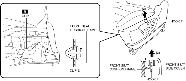
3. Remove clip E from the front seat cushion frame.
ac9wzw00005542
|
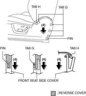
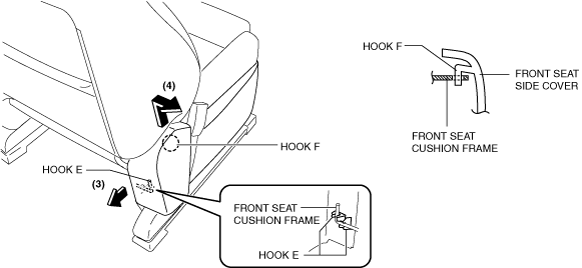
4. Pull up the front seat side cover in the direction of the arrow (3) shown in the figure and set hook F aside.
5. Pull the front seat side cover in the direction of the arrow (4) shown in the figure and disengage the tabs G and H, and the pin.
ac9wzw00005243
|
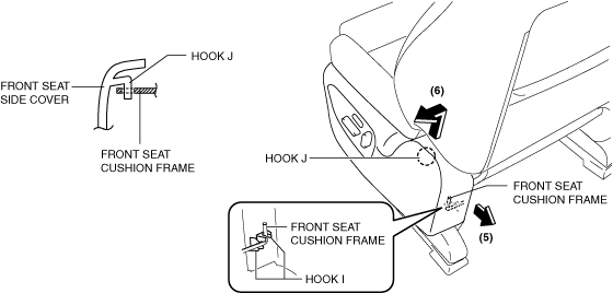
6. Pull the front seat side cover in the direction of the arrow (5) shown in the figure and set hook I aside.
ac9wzw00005543
|
7. Pull the front seat side cover in the direction of the arrow (6) shown in the figure and set hook J aside.
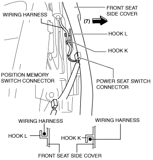
8. Disconnect the power seat switch connector (with power seat) and the position memory switch connector. (With position memory)
ac5uuw00004473
|
9. Set the wiring harness aside from hooks K and L, and remove the front seat side cover in the direction of the arrow (7) shown in the figure.
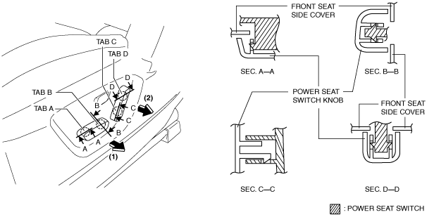
10. Pull the power seat switch knob in the direction of the arrow (1) shown in the figure, and remove it while disengaging tabs A and B.
ac5uuw00004053
|
11. Pull the power seat switch knob in the direction of the arrow (2) shown in the figure, and remove it while disengaging tabs C and D.
12. Remove the power seat switch. (See POWER SEAT SWITCH REMOVAL/INSTALLATION.)
13. Remove the position memory switch. (With position memory system) (See POSITION MEMORY SWITCH REMOVAL/INSTALLATION.)
14. Install in the reverse order of removal.
15. When the passenger's seat is removed, perform the DTC inspection for the SAS control module using the M-MDS and verify that no DTCs are displayed. (See DTC INSPECTION [SAS CONTROL MODULE].)
Without power seat system
1. Switch the ignition off (LOCK).
2. Disconnect the negative battery terminal and wait for 1 min. (See NEGATIVE BATTERY TERMINAL DISCONNECTION/CONNECTION.)
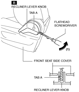
3. Move the flathead screwdriver wrapped in protective tape in the direction of the arrow (1) shown in the figure and disengage tab A.
ac5uuw00004054
|
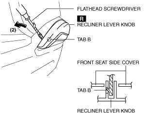
4. Move the flathead screwdriver wrapped in protective tape in the direction of the arrow (2) shown in the figure and disengage tab B.
ac5uuw00002863
|
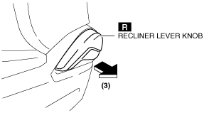
5. Remove the recliner lever knob in the direction of the arrow (3) shown in the figure.
ac5uuw00002864
|
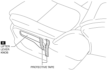
6. Affix the protective tape to the position shown in the figure.
ac5uuw00002899
|
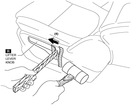
7. Using a wood slab, tap the end of the lifter lever knob with the plastic hammer and remove it in the direction of the arrow (4).
ac5uuw00004055
|
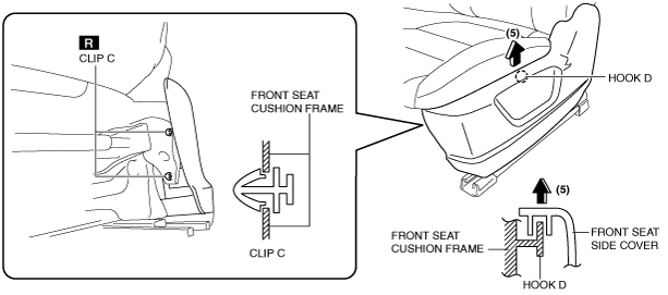
8. Remove clip C from the front seat cushion frame.
ac5uuw00002866
|
9. Pull up the front seat side cover in the direction of the arrow (5) shown in the figure and set hook D aside.
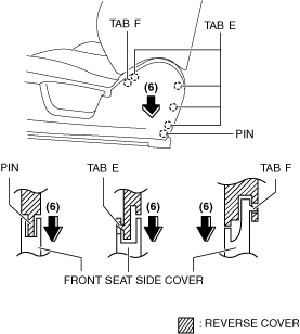
10. Pull the front seat side cover in the direction of the arrow (6) shown in the figure and disengage the tabs E and F, and the pin.
ac9wzw00005244
|
11. Pull the front seat side cover in the direction of the arrow (7) shown in the figure and set hook H aside.
ac5uuw00002020
|
12. Pull the front seat side cover in the direction of the arrow (8) shown in the figure and set hook I aside.
13. Remove the front seat side cover.
14. Install in the reverse order of removal.
15. When the passenger's seat is removed, perform the DTC inspection for the SAS control module using the M-MDS and verify that no DTCs are displayed. (See DTC INSPECTION [SAS CONTROL MODULE].)
Rear Console Side
1. Switch the ignition off (LOCK).
2. Disconnect the negative battery terminal and wait for 1 min. (See NEGATIVE BATTERY TERMINAL DISCONNECTION/CONNECTION.)
3. Remove the front seat. (See FRONT SEAT REMOVAL/INSTALLATION.)
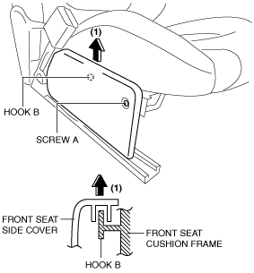
4. Remove the screw A.
ac5uuw00002021
|
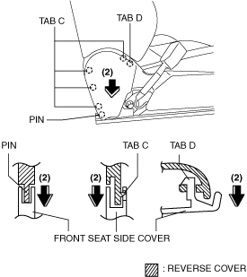
5. Pull up the front seat side cover in the direction of the arrow (1) shown in the figure and set hook B aside.
6. Pull the front seat side cover in the direction of the arrow (2) shown in the figure and disengage the tabs C and D, and the pin.
ac9wzw00005245
|
7. Pull the front seat side cover in the direction of the arrow (3) shown in the figure and set hook E aside.
ac5uuw00004059
|
8. Pull the front seat side cover in the direction of the arrow (4) shown in the figure and set hook F aside.
9. Remove the front seat side cover.
10. Install in the reverse order of removal.
11. When the passenger's seat is removed, perform the DTC inspection for the SAS control module using the M-MDS and verify that no DTCs are displayed. (See DTC TABLE [SAS CONTROL MODULE].)