 |
ac9wzw00004032
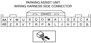
PARKING ASSIST UNIT INSPECTION
id092200041900
1. Disconnect the negative battery terminal. (See NEGATIVE BATTERY TERMINAL DISCONNECTION/CONNECTION.)
2. Remove the glove compartment. (See GLOVE COMPARTMENT REMOVAL/INSTALLATION.)
3. Remove the parking assist unit. (See PARKING ASSIST UNIT REMOVAL/INSTALLATION.)
4. Connect the negative battery terminal. (See NEGATIVE BATTERY TERMINAL DISCONNECTION/CONNECTION.)
5. Verify that the voltages of each of the terminals are as indicated in the terminal voltage table (reference).
Terminal Voltage Table (Reference)
ac9wzw00004032
|
|
Terminal |
Signal name |
Connected to |
Test condition |
Voltage (V) |
Inspection item |
|
|---|---|---|---|---|---|---|
|
A
|
Rear ultrasonic sensor
|
Rear ultrasonic sensor (LH)
|
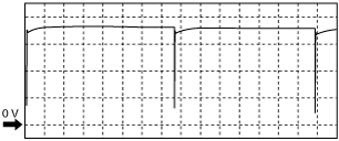
Wave pattern (See Inspection Using an Oscilloscope (reference).)
|
• Rear ultrasonic sensor (LH)
• Related wiring harness
|
||
|
B
|
Rear ultrasonic sensor GND
|
Rear ultrasonic sensor (LH)
|
Under any condition
|
1.0 or less
|
• Rear ultrasonic sensor (LH)
• Related wiring harness
|
|
|
C
|
Rear ultrasonic sensor
|
Rear ultrasonic sensor (RH)
|
Wave pattern (See Inspection Using an Oscilloscope (reference).)
|
• Rear ultrasonic sensor (RH)
• Related wiring harness
|
||
|
D
|
Rear ultrasonic sensor GND
|
Rear ultrasonic sensor (RH)
|
Under any condition
|
1.0 or less
|
• Rear ultrasonic sensor (RH)
• Related wiring harness
|
|
|
E
|
Rear ultrasonic sensor
|
Rear corner ultrasonic sensor (LH)
|
Wave pattern (See Inspection Using an Oscilloscope (reference).)
|
• Rear corner ultrasonic sensor (LH)
• Related wiring harness
|
||
|
F
|
Rear corner ultrasonic sensor GND
|
Rear corner ultrasonic sensor
|
Under any condition
|
1.0 or less
|
• Rear corner ultrasonic sensor
• Related wiring harness
|
|
|
G
|
Rear ultrasonic sensor
|
Rear corner ultrasonic sensor (RH)
|
Wave pattern (See Inspection Using an Oscilloscope (reference).)
|
• Rear corner ultrasonic sensor (RH)
• Related wiring harness
|
||
|
H
|
—
|
—
|
—
|
—
|
—
|
|
|
I*1
|
Front ultrasonic sensor
|
Front corner ultrasonic sensor (LH)
|
Wave pattern (See Inspection Using an Oscilloscope (reference).)
|
• Front corner ultrasonic sensor (LH)
• Related wiring harness
|
||
|
J*1
|
Front ultrasonic sensor GND
|
L.H.D.R.H.D.
• Front ultrasonic sensor (LH), (RH)
• Front corner ultrasonic sensor (LH), (RH)
• Front corner ultrasonic sensor (LH)
|
Under any condition
|
1.0 or less
|
L.H.D.R.H.D.
• Front ultrasonic sensor (LH), (RH)
• Front corner ultrasonic sensor (LH), (RH)
• Related wiring harness
• Front corner ultrasonic sensor (LH)
• Related wiring harness
|
|
|
K*1
|
Front ultrasonic sensor
|
Front ultrasonic sensor (LH)
|
Wave pattern (See Inspection Using an Oscilloscope (reference).)
|
• Front ultrasonic sensor (LH)
• Related wiring harness
|
||
|
L*2
|
Front ultrasonic sensor GND
|
Front ultrasonic sensor (LH)
|
Under any condition
|
1.0 or less
|
• Front ultrasonic sensor (LH)
• Related wiring harness
|
|
|
M*1
|
Front ultrasonic sensor
|
Front ultrasonic sensor (RH)
|
Wave pattern (See Inspection Using an Oscilloscope (reference).)
|
• Front ultrasonic sensor (RH)
• Related wiring harness
|
||
|
N*2
|
Front ultrasonic sensor GND
|
Front ultrasonic sensor (RH)
|
Under any condition
|
1.0 or less
|
• Front ultrasonic sensor (RH)
• Related wiring harness
|
|
|
O*1
|
Front corner ultrasonic sensor
|
Front corner ultrasonic sensor (RH)
|
Wave pattern (See Inspection Using an Oscilloscope (reference).)
|
• Front corner ultrasonic sensor (RH)
• Related wiring harness
|
||
|
P*2
|
Front corner ultrasonic sensor GND
|
Front corner ultrasonic sensor (RH)
|
Under any condition
|
1.0 or less
|
• Front corner ultrasonic sensor (RH)
• Related wiring harness
|
|
|
Q
|
GND
|
Body ground
|
Under any condition
|
1.0 or less
|
• Body ground
• Related wiring harness
|
|
|
R
|
—
|
—
|
—
|
—
|
—
|
|
|
S
|
—
|
—
|
—
|
—
|
—
|
|
|
T
|
—
|
—
|
—
|
—
|
—
|
|
|
U
|
Power supply (IG1)*3
|
Ignition relay (IG1_STAB)
|
Ignition switched ON (engine off or on)
|
B+
|
• Ignition relay (IG1_STAB)
• Related wiring harness
|
|
|
Ignition switched off or ACC
|
1.0 or less
|
|||||
|
Power supply (IG1)*4
|
IG1 relay
|
Ignition switched ON (engine off or on)
|
B+
|
• C/U IG1 15A fuse
• IG1 relay
• Related wiring harness
|
||
|
Ignition switched off or ACC
|
1.0 or less
|
|||||
|
V
|
Parking sensor switch
|
Cluster switch
|
Ignition switched ON (engine off or on)
|
Parking sensor switch ON
|
B+
|
• Cluster switch
• Related wiring harnesses
|
|
Parking sensor switch OFF
|
1.0 or less
|
|||||
|
W
|
Rear parking sensor buzzer
|
Rear parking sensor buzzer
|
Ignition switched ON (engine off or on)
|
B+
|
• Rear parking sensor buzzer
• Related wiring harness
|
|
|
Ignition switched off or ACC
|
1.0 or less
|
|||||
|
X
|
Rear parking sensor buzzer GND
|
Rear parking sensor buzzer
|
Ignition switched ON (engine off or on)
|
Buzzer sounding
|
1.0 or less
|
• Rear parking sensor buzzer
• Related wiring harness
|
|
Buzzer stopped
|
B+
|
|||||
|
Y
|
Front parking sensor buzzer
|
Front parking sensor buzzer
|
Ignition switched ON (engine off or on)
|
B+
|
• Front parking sensor buzzer
• Related wiring harness
|
|
|
Ignition switched off or ACC
|
1.0 or less
|
|||||
|
Z
|
Front parking sensor buzzer GND
|
Front parking sensor buzzer
|
Ignition switched ON (engine off or on)
|
Buzzer sounding
|
1.0 or less
|
• Front parking sensor buzzer
• Related wiring harness
|
|
Buzzer stopped
|
B+
|
|||||
|
AA
|
CAN_H
|
CAN system related module
|
Terminal used for communication therefore determination based on terminal voltage is not possible.
|
|||
|
AB
|
CAN_L
|
CAN system related module
|
Terminal used for communication therefore determination based on terminal voltage is not possible.
|
|||
Inspection Using an Oscilloscope (reference)
L.H.D.
|
Oscilloscope setting: |
Terminal |
|||||||||
|---|---|---|---|---|---|---|---|---|---|---|
|
Ignition |
Shift lever position |
Vehicle speed |
Front corner ultrasonic sensor (LH) |
Front ultrasonic sensor (LH) |
Front ultrasonic sensor (RH) |
Front corner ultrasonic sensor (RH) |
Rear corner ultrasonic sensor (LH) |
Rear ultrasonic sensor (LH) |
Rear ultrasonic sensor (RH) |
Rear corner ultrasonic sensor (RH) |
|
ON (engine off or on)
|
Except R position
|
0—15 km/h {0—9.3 mph} or less
|
I—J
|
K—J
|
M—J
|
O—J
|
—
|
—
|
—
|
—
|
|
R position
|
I—J
|
—
|
—
|
O—J
|
E—F
|
A—B
|
C—D
|
G—F
|
||
R.H.D.
|
Oscilloscope setting: |
Terminal |
|||||||||
|---|---|---|---|---|---|---|---|---|---|---|
|
Ignition |
Shift lever position |
Vehicle speed |
Front corner ultrasonic sensor (LH) |
Front ultrasonic sensor (LH) |
Front ultrasonic sensor (RH) |
Front corner ultrasonic sensor (RH) |
Rear corner ultrasonic sensor (LH) |
Rear ultrasonic sensor (LH) |
Rear ultrasonic sensor (RH) |
Rear corner ultrasonic sensor (RH) |
|
ON (engine off or on)
|
Except R position
|
0—15 km/h {0—9.3 mph} or less
|
I—J
|
K—L
|
M—N
|
P—O
|
—
|
—
|
—
|
—
|
|
R position
|
I—J
|
—
|
—
|
P—O
|
E—F
|
A—B
|
C—D
|
G—F
|
||
am6zzw00006971
|