FOREWORD [RADAR UNIT]
id1502a6017100
Special Service Tool (SST)
|
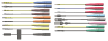
49US 15 1A0
PROBE KIT
|
 |
• When system component parts are replaced/removed/installed, the radar unit aiming adjustment and initialization settings for the sensor and the module must be performed. Perform the relevant initial setting servicing referring to the corresponding removal/installation procedure.
• The radar unit is a control device which monitors the vehicle ahead using radio waves emitted from the radar unit which reflect off the vehicle ahead and return to the radio sensor part of the control module. The radar unit may not operate normally under the following conditions:
Effects of traffic conditions
-
? Sudden change in distance with vehicle ahead such as another vehicle cutting into drive lane
? Poor roads, curves, changes in slope (detection of different distance from actual vehicle distance due to vehicle ahead being temporarily out of detection area)
Effects of weather conditions
-
? Rain, snow, or fog (beads of water, radio reception distortion due to cast-off from vehicle ahead)
Effects of driving conditions
-
? Load conditions (vehicle ahead is out of detection area of radar unit due to large change in vehicle posture)
Effects from maintenance condition of vehicle
-
? Dirt on radiator grille ornament, modifications, application of stickers (including transparent types), scratches, or damage
Effects of vehicle ahead
-
? Excessively dirty vehicle, special type of vehicle (such as unloaded trailer) (reception of reflected radio waves is weak)
• If there is any vehicle malfunction complaint lodged by a customer, perform malfunction diagnosis according to the troubleshooting procedure.
Troubleshooting procedure
Action for Non-repeatable Malfunction
• If the malfunction does not recur, verify the malfunction cause by performing the following actions:
-
? Based on the repair order form, attempt to drive the vehicle or perform tests to replicate the malfunction, record the data at that time, and detect the malfunction cause.
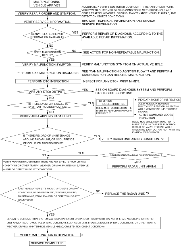
? Shake the wiring harness or connector of the electrical component which is suspected to be the cause of the malfunction, and inspect for malfunction or occurrence of any DTCs.
? Inspect the female terminals on the connector of the electric component which is suspected to be the cause of the malfunction for poor connection. (See
ELECTRICAL SYSTEM.)
-
Note
-
• SST (Reference): PROBE KIT (49US 15 1A0)