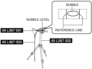
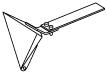
49 L067 001
Reflector
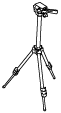
49 L067 002
Tripod
49 L067 003
Plum-bob

BLIND SPOT MONITORING (BSM) RADAR TEST
id152000003000
Special Service Tool (SST)
|
49 L067 001
Reflector
|
|
49 L067 002
Tripod
|
|
49 L067 003
Plum-bob
|
|
Radar test procedure
1. Empty the vehicle by having all occupants leave the vehicle and remove all the cargo except for the spare tire, jack and tools equipped on the vehicle.
2. Adjust the air pressure of each tire to the specified value. (See WHEEL AND TIRE SPECIFICATION.)
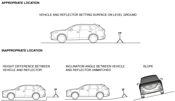
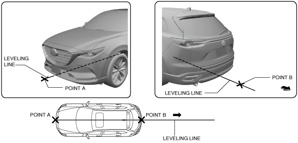
3. Move the vehicle to level ground.
ac9uuw00007376
|
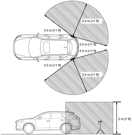
4. Verify that there are no obstructions which interfere with radar emissions such as metal objects in the radar emission area shown in the figure.
ac9uuw00007377
|
5. Using the M-MDS, perform a DTC inspection of the BSM control modules and verify that no DTCs are displayed. (See DTC INSPECTION [BLIND SPOT MONITORING (BSM) CONTROL MODULE].)
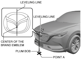
6. Adjust the SST (plum-bob) so that it is aligned with the center of the brand emblem, determine the center position at the front of the vehicle, and mark the center position (point A) on the floor surface.
ac9uuw00007378
|
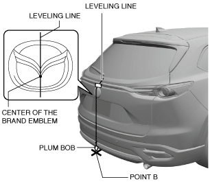
7. Adjust the SST (plum-bob) so that it is aligned with the center of the brand emblem, determine the center position at the rear of the vehicle, and mark the center position (point B) on the floor surface.
ac9uuw00007379
|
8. Secure the end of the leveling line over point A.
ac9uuw00007380
|
9. Pull the unsecured end of the leveling line over the vehicle and to the rear and adjust it so that passes over point B.
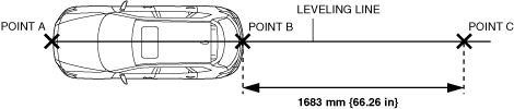
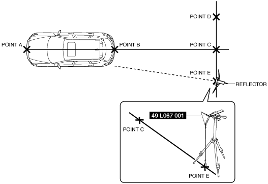
10. Mark the line (position C) within the range of 1683 mm {66.26 in}from point B and in the direction rearward of the vehicle.
ac9wzw00005272
|
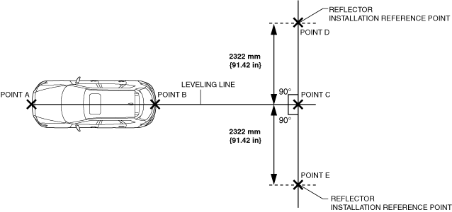
11. Mark the points (points D and E) (SST (reflector) installation reference points) 2322 mm {91.42 in}from point C on the line which runs perpendicular to the vehicle center line (SST (reflector) installation reference point).
ac9wzw00005273
|
12. Pull the connected points D, C and E lines (SST (reflector) installation line).
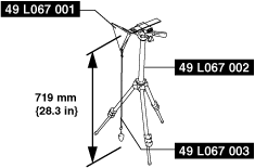
13. Install the SST (reflector and plum bob) to the SST (tripod).
ac9wzw00005274
|
14. Adjust so that the height of the SST (reflector) from the floor surface is 719 mm {28.3 in}.
15. Level the SST (reflector) by adjusting the leveling bubble on the SST (tripod) so that it is centered on the bubble reference line.
ac5wzw00007774
|
16. Align point D or point E with the end of the SST (plum bomb).
ac9uuw00007383
|
17. Adjust the reflecting surface of the SST (reflector) so that it faces the radar emission surface (near a rear bumper corner) of BSM control module.
18. Perform the radar test using the M-MDS.
19. Connect the M-MDS to the DLC-2.
20. After vehicle identification, the following can be selected from the M-MDS initialization screen.
21. Select either the left or right rear BSM control module and perform the radar test according to the instructions on the M-MDS screen.
22. Verify the M-MDS display.
|
Step |
Inspection |
Action |
|
|---|---|---|---|
|
1
|
VERIFY REFLECTOR POSITION
• Verify if the reflector installation position is correct.
• Is the reflector set in the correct position?
|
Yes
|
Go to the next step.
|
|
No
|
Set the reflector in the correct position and perform the BSM radar test.
|
||
|
2
|
INSPECT REAR BUMPER
• Remove the rear bumper.
• Perform the BSM radar test.
• Is "Procedure completed correctly." displayed?
|
Yes
|
Replace the rear bumper and perform the BSM radar test.
|
|
No
|
Go to the next step.
|
||
|
3
|
VERIFY IF BSM CONTROL MODULE OR BSM BRACKET IS MIS-INSTALLED AND IF THERE IS DISTORTION TO VEHICLE INSTALLATION SURFACE
• Verify whether a BSM control module or BSM bracket has been mis-installed, and if there is distortion to the vehicle installation surface.
• Is there poor installation or distortion?
|
Yes
|
Repair or replace the malfunctioning part and perform the BSM radar test.
|
|
No
|
Go to the next step.
|
||
|
4
|
RE-PERFORM THE BSM RADAR TEST
• Perform the BSM radar test.
• Repeat the M-MDS operation for the BSM radar test 2 or 3 times (Steps 21 to 22).
• Is "Procedure completed correctly." displayed?
|
Yes
|
BSM radar test is completed.
|
|
No
|
Replace the BSM control module.
|
||