49 L067 006
Plumb bob

49 JP04 001
Target marker

360°VIEW MONITOR SYSTEM AIMING
id152000010200
Special service tool (SST)
|
49 L067 006
Plumb bob
|
|
49 JP04 001
Target marker
|
|
Preparation Before Servicing
1. Empty the vehicle by having all occupants leave the vehicle and remove all the cargo except for the spare tire, jack and tools equipped on the vehicle.
2. Adjust the air pressure of each tire to the specified value. (See WHEEL AND TIRE SPECIFICATION.)
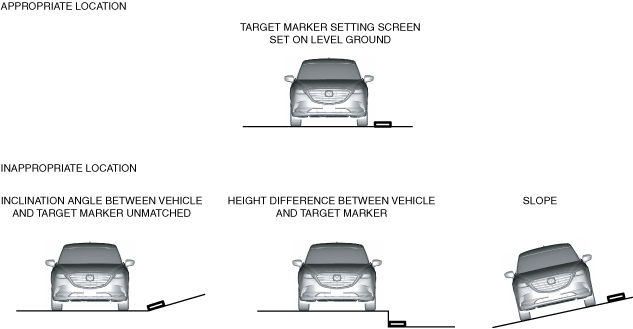
3. Move the vehicle to level ground.
ac9wzw00005301
|
4. Using the M-MDS, perform a DTC inspection for 360° view monitor unit and verify that no DTCs are displayed. (See DTC INSPECTION [360°VIEW MONITOR CONTROL MODULE].)
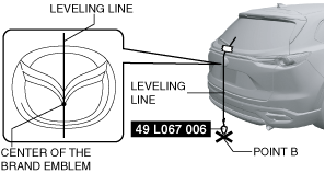
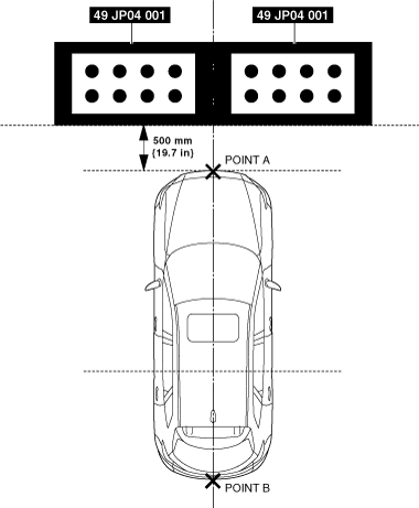
5. Adjust the SST so that it is aligned with the center of the brand emblem, determine the center position at the front of the vehicle, and mark the center position (point A) on the floor surface.
ac9wzw00005302
|
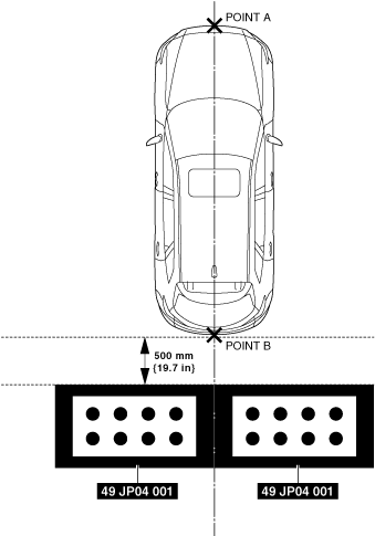
6. Adjust the SST so that it is aligned with the center of the brand emblem, determine the center position at the rear of the vehicle, and mark the center position (point B) on the floor surface.
ac9wzw00005303
|
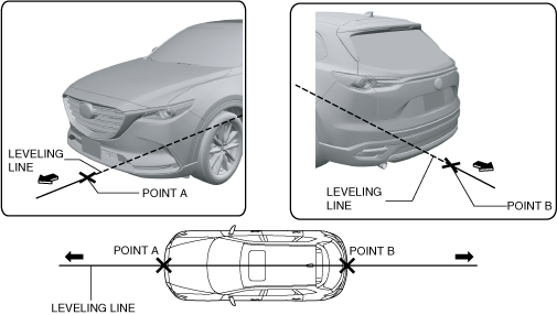
7. Pull the leveling line towards the front and rear of the vehicle and adjust it so that it passes over points A and B.
ac9wzw00005304
|
8. Secure the leveling line.
9. If the 360° view monitor control module is replaced, go to the 360° view monitor system aiming procedure. (See 360° View Monitor System Aiming (Batch Aiming) Procedure.)
10. If the 360° view monitor control module is not replaced, go to the 360° view monitor system screen display verification procedure. (See 360° View Monitor System Screen Display Verification Procedure.)
360° View Monitor System Screen Display Verification Procedure
1. Perform the preparation before servicing. (See Preparation Before Servicing.)
2. If the 360° view monitor control module is replaced, perform the 360° view monitor system aiming procedure. (See 360° View Monitor System Aiming (Batch Aiming) Procedure.)
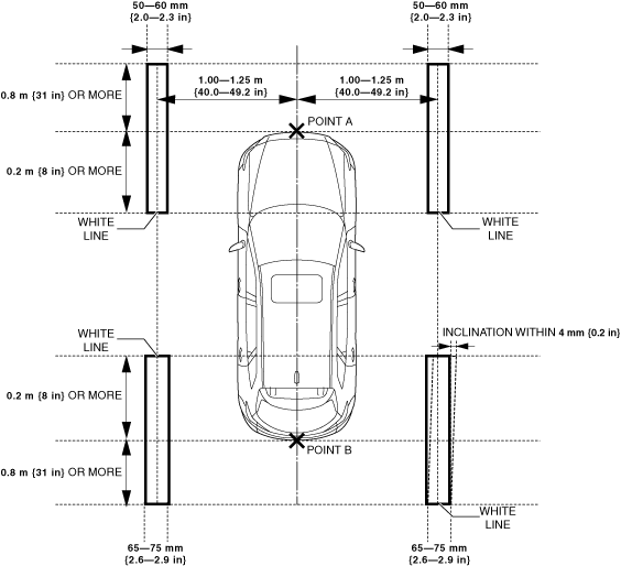
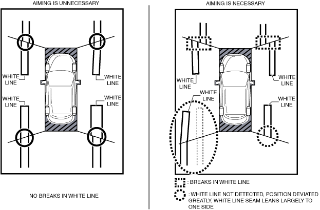
3. Position the white lines at the positions shown in the figure.
ac9wzw00005305
|
4. Verify that all the doors (front door, rear door) and the liftgate are closed.
5. Verify that the outer mirrors are unfolded.
6. Switch the ignition ON (engine off or on).
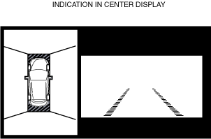
7. Display the screen of the 360° view monitor system in the center display by pressing the 360° view monitor switch.
ac5wzw00011926
|
8. Verify that there are no breaks in the seams of the white lines in the display screen of the center display.
ac5wzw00011927
|
360° View Monitor System Aiming (Batch Aiming) Procedure
1. Perform the preparation before servicing. (See Preparation Before Servicing.)
2. Perform the 360° view monitor system screen display verification procedure. (See 360° View Monitor System Screen Display Verification Procedure.)
3. Position the SSTs at the positions shown in the figure.
ac9wzw00005306
|
4. Connect the M-MDS to the DLC-2.
5. After vehicle identification is completed, select the following from the M-MDS initial screen.
6. Perform the 360° view monitor system aiming according to the directions on the M-MDS.
7. Verify the M-MDS display.
|
Error code |
Detection Condition |
|---|---|
|
03
|
Target marker No.1 of rear mount camera is not detected
|
|
04
|
Target marker No.2 of rear mount camera is not detected
|
|
05
|
Target markers No.1 and 2 of rear mount camera are not detected
|
|
06
|
Target marker No.1 of side camera (LH) is not detected
|
|
07
|
Target marker No.2 of side camera (LH) is not detected
|
|
08
|
Target markers No.1 and 2 of side camera (LH) are not detected
|
|
09
|
Target marker No.1 of front camera is not detected
|
|
0A
|
Target marker No.2 of front camera is not detected
|
|
0B
|
Target markers No.1 and 2 of front camera are not detected
|
|
0C
|
Target marker No.1 of side camera (RH) is not detected
|
|
0D
|
Target marker No.2 of side camera (RH) is not detected
|
|
0E
|
Target markers No.1 and 2 of side camera (RH) are not detected
|
|
0F
|
Target marker moves during aiming
|
|
10
|
Input vehicle value exceeds specification
|
|
11
|
Aiming procedure is not completed
|
|
12
|
Aiming result is required for 360° view monitor control module with aiming not completed
|
|
13
|
Aiming procedure is canceled
|
|
14
|
Power outer mirrors are retracted
|
|
15
|
Aiming is not possible due to malfunction in 360° view monitor control module
|
|
16
|
360° view monitor control module cannot receive rear mount camera images
|
|
17
|
360° view monitor control module cannot receive side camera (LH) images
|
|
18
|
360° view monitor control module cannot receive front camera images
|
|
19
|
360° view monitor control module cannot receive side camera (RH) images
|
|
1A
|
Power supply to camera insufficient
|
|
FF
|
Aiming cannot be performed due to communication error
|
Error code 03/04/05/06/07/08/09/0A/0B/0C/0D/0E/0F/10
|
Step |
Inspection |
Action |
|
|---|---|---|---|
|
1
|
VERIFY TARGET MARKER SETTING ENVIRONMENT AND POSITION
• Verify the following.
• Is there a malfunction?
|
Yes
|
Repair the malfunctioning location and go to the next step.
|
|
No
|
Go to the next step.
|
||
|
2
|
PERFORM 360° VIEW MONITOR SYSTEM AIMING
• Perform the 360° view monitor system aiming.
• Was the 360° view monitor system aiming procedure completed correctly?
|
Yes
|
The 360° view monitor system aiming is completed. Perform the 360° view monitor system screen display verification procedure.
|
|
No
|
If error code 03/04/05/06/07/08/09/0A/0B/0C/0D/0E/0F/10 is displayed
• Go to the next step.
If code other than error code 03/04/05/06/07/08/09/0A/0B/0C/0D/0E/0F/10 is displayed
• Go to the procedure for the displayed error code.
|
||
|
3
|
VERIFY DTCs
• Perform the DTC inspection.
• Is a DTC displayed?
|
Yes
|
Go to the applicable DTC inspection.
|
|
No
|
If the 360° view monitor system aiming is not completed correctly after performing the 360° view monitor system aiming again, replace the 360° view monitor control module.
|
||
Error code 11/12/13/15/16/17/18/19/1A/FF
|
Step |
Inspection |
Action |
|
|---|---|---|---|
|
1
|
PERFORM 360° VIEW MONITOR SYSTEM AIMING
• Perform the 360° view monitor system aiming.
• Was the 360° view monitor system aiming procedure completed correctly?
|
Yes
|
The 360° view monitor system aiming is completed. Perform the 360° view monitor system screen display verification procedure.
|
|
No
|
If error code 11/12/13/15/16/17/18/19/1A/FF is displayed
• Go to the next step.
If code other than error code 11/12/13/15/16/17/18/19/1A/FF is displayed
• Go to the procedure for the displayed error code.
|
||
|
2
|
VERIFY DTCs
• Perform the DTC inspection.
• Is a DTC displayed?
|
Yes
|
Go to the applicable DTC inspection.
|
|
No
|
If the 360° view monitor system aiming is not completed correctly after performing the 360° view monitor system aiming again, replace the 360° view monitor control module.
|
||
Error code 14
|
Step |
Inspection |
Action |
|
|---|---|---|---|
|
1
|
VERIFY POWER OUTER MIRROR FOLD/UNFOLD CONDITION
• Are the power outer mirrors unfolded?
|
Yes
|
Go to the next step.
|
|
No
|
Unfold the power outer mirrors, then go to the next step.
|
||
|
2
|
PERFORM 360° VIEW MONITOR SYSTEM AIMING
• Perform the 360° view monitor system aiming.
• Was the 360° view monitor system aiming procedure completed correctly?
|
Yes
|
The 360° view monitor system aiming is completed. Perform the 360° view monitor system screen display verification procedure.
|
|
No
|
If error code 14 is displayed
• Go to the next step.
If code other than error code 14 is displayed
• Go to the procedure for the displayed error code.
|
||
|
3
|
VERIFY DTCs
• Perform the DTC inspection.
• Is a DTC displayed?
|
Yes
|
Go to the applicable DTC inspection.
|
|
No
|
If the 360° view monitor system aiming is not completed correctly after performing the 360° view monitor system aiming again, replace the 360° view monitor control module.
|
||
Front Camera Aiming Procedure
1. Perform the preparation before servicing. (See Preparation Before Servicing.)
2. Perform the 360° view monitor system screen display verification procedure. (See 360° View Monitor System Screen Display Verification Procedure.)
3. Position the SSTs at the positions shown in the figure.
ac9wzw00005307
|
4. Connect the M-MDS to the DLC-2.
5. After vehicle identification is completed, select the following from the M-MDS initial screen.
6. Perform the front camera aiming procedure according to the directions on the M-MDS.
7. Verify the M-MDS display.
|
Error code |
Detection Condition |
|---|---|
|
09
|
Target marker No.1 of front camera is not detected
|
|
0A
|
Target marker No.2 of front camera is not detected
|
|
0B
|
Target markers No.1 and 2 of front camera are not detected
|
|
0F
|
Target marker moves during aiming
|
|
10
|
Input vehicle value exceeds specification
|
|
11
|
Aiming procedure is not completed
|
|
12
|
Aiming result is required for 360° view monitor control module with aiming not completed
|
|
13
|
Aiming procedure is canceled
|
|
15
|
Aiming is not possible due to malfunction in 360° view monitor control module
|
|
18
|
360° view monitor control module cannot receive front camera images
|
|
1A
|
Power supply to camera insufficient
|
|
FF
|
Aiming cannot be performed due to communication error
|
Error code 09/0A/0B/0F/10
|
Step |
Inspection |
Action |
|
|---|---|---|---|
|
1
|
VERIFY TARGET MARKER SETTING ENVIRONMENT AND POSITION
• Verify the following.
• Is there a malfunction?
|
Yes
|
Repair the malfunctioning location and go to the next step.
|
|
No
|
Go to the next step.
|
||
|
2
|
PERFORM FRONT CAMERA AIMING
• Perform the front camera aiming.
• Was the front camera aiming procedure completed correctly?
|
Yes
|
The front camera aiming is completed. Perform the 360° view monitor system screen display verification procedure.
|
|
No
|
If error code 09/0A/0B/0F/10 is displayed
• Go to the next step.
If code other than error code 09/0A/0B/0F/10 is displayed
• Go to the procedure for the displayed error code.
|
||
|
3
|
VERIFY DTCs
• Perform the DTC inspection.
• Is a DTC displayed?
|
Yes
|
Go to the applicable DTC inspection.
|
|
No
|
If the front camera aiming is not completed correctly after performing the front camera aiming again, replace the 360° view monitor control module.
|
||
Error code 11/12/13/15/18/1A/FF
|
Step |
Inspection |
Action |
|
|---|---|---|---|
|
1
|
PERFORM FRONT CAMERA AIMING
• Perform the front camera aiming.
• Was the front camera aiming procedure completed correctly?
|
Yes
|
The front camera aiming is completed. Perform the 360° view monitor system screen display verification procedure.
|
|
No
|
If error code 11/12/13/15/18/1A/FF is displayed
• Go to the next step.
If code other than error code 11/12/13/15/18/1A/FF is displayed
• Go to the procedure for the displayed error code.
|
||
|
2
|
VERIFY DTCs
• Perform the DTC inspection.
• Is a DTC displayed?
|
Yes
|
Go to the applicable DTC inspection.
|
|
No
|
If the front camera aiming is not completed correctly after performing the front camera aiming again, replace the 360° view monitor control module.
|
||
Side Camera Aiming Procedure
1. Perform the preparation before servicing. (See Preparation Before Servicing.)
2. Perform the 360° view monitor system screen display verification procedure. (See 360° View Monitor System Screen Display Verification Procedure.)
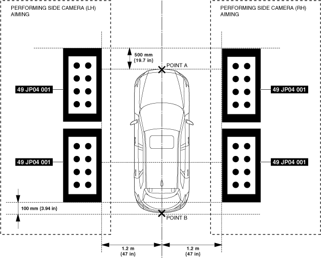
3. Position the SSTs at the positions shown in the figure.
ac9wzw00005308
|
4. Connect the M-MDS to the DLC-2.
5. After vehicle identification is completed, select the following from the M-MDS initial screen.
6. Perform side camera aiming procedure according to the directions on the M-MDS.
7. Verify the M-MDS display.
|
Error code |
Detection Condition |
|---|---|
|
06
|
Target marker No.1 of side camera (LH) is not detected
|
|
07
|
Target marker No.2 of side camera (LH) is not detected
|
|
08
|
Target markers No.1 and 2 of side camera (LH) are not detected
|
|
0C
|
Target marker No.1 of side camera (RH) is not detected
|
|
0D
|
Target marker No.2 of side camera (RH) is not detected
|
|
0E
|
Target markers No.1 and 2 of side camera (RH) are not detected
|
|
0F
|
Target marker moves during aiming
|
|
10
|
Input vehicle value exceeds specification
|
|
11
|
Aiming procedure is not completed
|
|
12
|
Aiming result is required for 360° view monitor control module with aiming not completed
|
|
13
|
Aiming procedure is canceled
|
|
14
|
Power outer mirrors are retracted
|
|
15
|
Aiming is not possible due to malfunction in 360° view monitor control module
|
|
17
|
360° view monitor control module cannot receive side camera (LH) images
|
|
19
|
360° view monitor control module cannot receive side camera (RH) images
|
|
1A
|
Power supply to camera insufficient
|
|
FF
|
Aiming cannot be performed due to communication error
|
Error code 06/07/08/0C/0D/0E/0F/10
|
Step |
Inspection |
Action |
|
|---|---|---|---|
|
1
|
VERIFY TARGET MARKER SETTING ENVIRONMENT AND POSITION
• Verify the following.
• Is there a malfunction?
|
Yes
|
Repair the malfunctioning location and go to the next step.
|
|
No
|
Go to the next step.
|
||
|
2
|
PERFORM SIDE CAMERA AIMING
• Perform the side camera aiming.
• Was the side camera aiming procedure completed correctly?
|
Yes
|
The side camera aiming is completed. Perform the 360° view monitor system screen display verification procedure.
|
|
No
|
If error code 06/07/08/0C/0D/0E/0F/10 is displayed
• Go to the next step.
If code other than error code 06/07/08/0C/0D/0E/0F/10 is displayed
• Go to the procedure for the displayed error code.
|
||
|
3
|
VERIFY DTCs
• Perform the DTC inspection.
• Is a DTC displayed?
|
Yes
|
Go to the applicable DTC inspection.
|
|
No
|
If the side camera aiming is not completed correctly after performing the side camera aiming again, replace the 360° view monitor control module.
|
||
Error code 11/12/13/15/17/19/1A/FF
|
Step |
Inspection |
Action |
|
|---|---|---|---|
|
1
|
PERFORM SIDE CAMERA AIMING
• Perform the side camera aiming.
• Was the side camera aiming procedure completed correctly?
|
Yes
|
The side camera aiming is completed. Perform the 360° view monitor system screen display verification procedure.
|
|
No
|
If error code 11/12/13/15/17/19/1A/FF is displayed
• Go to the next step.
If code other than error code 11/12/13/15/17/19/1A/FF is displayed
• Go to the procedure for the displayed error code.
|
||
|
2
|
VERIFY DTCs
• Perform the DTC inspection.
• Is a DTC displayed?
|
Yes
|
Go to the applicable DTC inspection.
|
|
No
|
If the side camera aiming is not completed correctly after performing the side camera aiming again, replace the 360° view monitor control module.
|
||
Error code 14
|
Step |
Inspection |
Action |
|
|---|---|---|---|
|
1
|
VERIFY POWER OUTER MIRROR FOLD/UNFOLD CONDITION
• Are the power outer mirrors unfolded?
|
Yes
|
Go to the next step.
|
|
No
|
Unfold the power outer mirrors, then go to the next step.
|
||
|
2
|
PERFORM SIDE CAMERA AIMING
• Perform the side camera aiming.
• Was the side camera aiming procedure completed correctly?
|
Yes
|
The side camera aiming is completed. Perform the 360° view monitor system screen display verification procedure.
|
|
No
|
If error code 14 is displayed
• Go to the next step.
If code other than error code 14 is displayed
• Go to the procedure for the displayed error code.
|
||
|
3
|
VERIFY DTCs
• Perform the DTC inspection.
• Is a DTC displayed?
|
Yes
|
Go to the applicable DTC inspection.
|
|
No
|
If the side camera aiming is not completed correctly after performing the side camera aiming again, replace the 360° view monitor control module.
|
||
Rear Mount Camera Aiming Procedure
1. Perform the preparation before servicing. (See Preparation Before Servicing.)
2. Perform the 360° view monitor system screen display verification procedure. (See 360° View Monitor System Screen Display Verification Procedure.)
3. Position the SSTs at the positions shown in the figure.
ac9wzw00005309
|
4. Connect the M-MDS to the DLC-2.
5. After vehicle identification is completed, select the following from the M-MDS initial screen.
6. Perform the rear mount camera aiming procedure according to the directions on the M-MDS.
7. Verify the M-MDS display.
|
Error code |
Detection Condition |
|---|---|
|
03
|
Target marker No.1 of rear mount camera is not detected
|
|
04
|
Target marker No.2 of rear mount camera is not detected
|
|
05
|
Target markers No.1 and 2 of rear mount camera are not detected
|
|
0F
|
Target marker moves during aiming
|
|
10
|
Input vehicle value exceeds specification
|
|
11
|
Aiming procedure is not completed
|
|
12
|
Aiming result is required for 360° view monitor control module with aiming not completed
|
|
13
|
Aiming procedure is canceled
|
|
15
|
Aiming is not possible due to malfunction in 360° view monitor control module
|
|
16
|
360° view monitor control module cannot receive rear mount camera images
|
|
1A
|
Power supply to camera insufficient
|
|
FF
|
Aiming cannot be performed due to communication error
|
Error code 03/04/05/0F/10
|
Step |
Inspection |
Action |
|
|---|---|---|---|
|
1
|
VERIFY TARGET MARKER SETTING ENVIRONMENT AND POSITION
• Verify the following.
• Is there a malfunction?
|
Yes
|
Repair the malfunctioning location and go to the next step.
|
|
No
|
Go to the next step.
|
||
|
2
|
PERFORM REAR MOUNT CAMERA AIMING
• Perform the rear mount camera aiming.
• Was the rear mount camera aiming procedure completed correctly?
|
Yes
|
The rear mount camera aiming is completed. Perform the 360° view monitor system screen display verification procedure.
|
|
No
|
If error code 03/04/05/0F/10 is displayed
• Go to the next step.
If code other than error code 03/04/05/0F/10 is displayed
• Go to the procedure for the displayed error code.
|
||
|
3
|
VERIFY DTCs
• Perform the DTC inspection.
• Is a DTC displayed?
|
Yes
|
Go to the applicable DTC inspection.
|
|
No
|
If the rear mount camera aiming is not completed correctly after performing the rear mount camera aiming again, replace the 360° view monitor control module.
|
||
Error code 11/12/13/15/16/1A/FF
|
Step |
Inspection |
Action |
|
|---|---|---|---|
|
1
|
PERFORM REAR MOUNT CAMERA AIMING
• Perform the rear mount camera aiming.
• Was the rear mount camera aiming procedure completed correctly?
|
Yes
|
The rear mount camera aiming is completed. Perform the 360° view monitor system screen display verification procedure.
|
|
No
|
If error code 11/12/13/15/16/1A/FF is displayed
• Go to the next step.
If code other than error code 11/12/13/15/16/1A/FF is displayed
• Go to the procedure for the displayed error code.
|
||
|
2
|
VERIFY DTCs
• Perform the DTC inspection.
• Is a DTC displayed?
|
Yes
|
Go to the applicable DTC inspection.
|
|
No
|
If the rear mount camera aiming is not completed correctly after performing the rear mount camera aiming again, replace the 360° view monitor control module.
|
||