 |
ac9uuw00008019
WHEEL HUB, STEERING KNUCKLE REMOVAL/INSTALLATION
id031100800400
1. Remove the wheel and tire. (See WHEEL AND TIRE REMOVAL/INSTALLATION.)
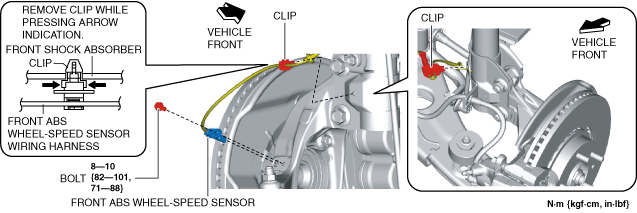
2. Disconnect the front ABS wheel-speed sensor wiring harness installed to the steering knuckle and set it aside. (See FRONT ABS WHEEL-SPEED SENSOR REMOVAL/INSTALLATION.)
ac9uuw00008019
|
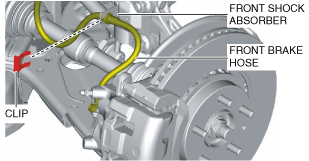
3. Remove the clip from the front shock absorber.
ac9uuw00008020
|
4. Remove the front brake hose from the front shock absorber.
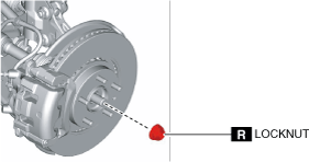
5. Remove the locknut. (See Locknut Removal Note.) (See Locknut Installation Note.)
ac9uuw00008021
|
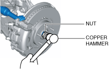
6. Install a spare nut onto the drive shaft.
7. Tap the nut with a copper hammer and separate the drive shaft from the axle.
ac9uuw00008022
|
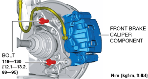
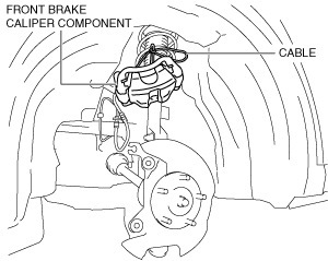
8. Remove the front brake caliper component installation bolts.
ac9uuw00008023
|
9. Remove the front brake caliper component and suspend it out of the way using a cable.
ac9uuw00008024
|
10. Remove the front disc plate. (See FRONT BRAKE (DISC) REMOVAL/INSTALLATION.)
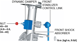
11. Remove the front stabilizer control link and dynamic damper from the front shock absorber.
ac9uuw00008025
|
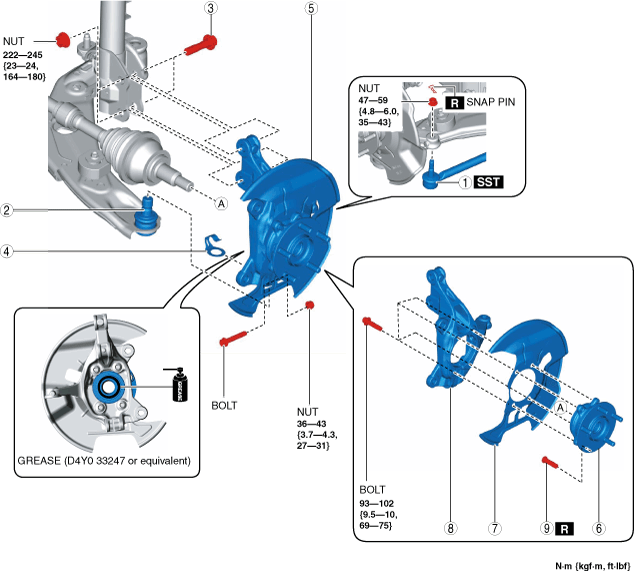
12. Remove in the order indicated in the table.
13. Install in the reverse order of removal.
14. When replacing the steering knuckle, inspect the wheel alignment and adjust it if necessary. (See FRONT WHEEL ALIGNMENT.)
ac9wzw00005700
|
|
1
|
Tie-rod end
(See TIE-ROD END REPLACEMENT.)
|
|
2
|
Front lower arm ball joint
|
|
3
|
Bolt (front shock absorber)
|
|
4
|
Spacer
|
|
5
|
Front wheel hub, dust cover, steering knuckle component
|
|
6
|
Front wheel hub
|
|
7
|
Dust cover
|
|
8
|
Steering knuckle
|
|
9
|
Front wheel hub bolt
|
Locknut Removal Note
1. Remove the locknut with the brake pedal depressed.
Front Wheel Hub, Dust Cover, Steering Knuckle Removal Note
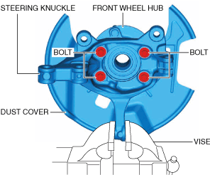
1. Secure the steering knuckle in a vise.
ac9uuw00008027
|
2. Remove the bolts and remove the front wheel hub and dust cover from the steering knuckle.
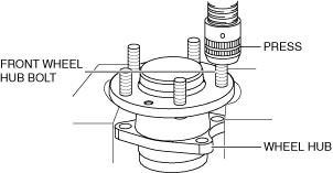
Front Wheel Hub Bolt Removal Note
1. Remove the front wheel hub bolt from the wheel hub using a press.
ac4ccw00000708
|
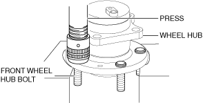
Front Wheel Hub Bolt Installation Note
1. Press in new front wheel hub bolt into the wheel hub using a press.
ac4ccw00000709
|
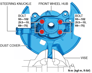
Front Wheel Hub, Dust Cover, Steering Knuckle Installation Note
1. Secure the steering knuckle in a vise.
ac9uuw00008028
|
2. Install the dust cover and front wheel hub to the steering knuckle and tighten the bolts to the specified torque.
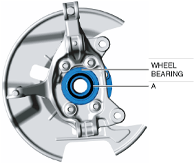
Front Wheel Hub, Dust Cover, Steering Knuckle Component Installation Note
1. Apply grease (D4Y0 33247 or equivalent) to the wheel bearing inner race and drive shaft contact surface (Area A in figure).
ac9uuw00008029
|
2. Install the front wheel hub, dust cover, steering knuckle component.
Bolt (Front Shock Absorber) Installation Note
1. Install the steering knuckle to the front shock absorber, insert the bolts from the direction indicated as follows, then tighten them to the specified torque.
Locknut Installation Note
1. If dust or grease is on the drive shaft thread area, wipe it off with a cloth.
2. Tighten the locknut using the following procedure and with the brake pedal depressed.