STEP
INSPECTION
ACTION
1
CONFIRM DSC HU/CM DTC
• Retrieve the DSC HU/CM DTC using the M-MDS.
(See DTC INSPECTION [DSC HU/CM].)
• Are any DTCs present?
Yes
Go to the applicable DTC inspection.
(See DTC TABLE [DSC HU/CM].)
No
Go to the next step.
2
VERIFY IF MALFUNCTION IS IN DSC HU/CM CONNECTOR FOR POOR CONNECTION OR ELSEWHERE
• Switch the ignition ON.
• Does the ABS warning light, brake warning light, TCS/DSC indicator light, and TCS OFF indicator light (without Off-road traction assist)/Off-road traction assist indicator light (with Off-road traction assist) turn off after 2 to 4 s?
Yes
Inspect the DSC HU/CM connector or terminal. (poor connection intermittently)
• If there is a malfunction, repair or replace any malfunctioning parts according to the inspection result.
No
Go to the next step.
3
INSPECT BATTERY VOLTAGE
• Switch the ignition OFF.
• Inspect the battery voltage.
(See BATTERY INSPECTION.)
• Is the battery voltage normal?
Yes
Go to the next step.
No
Recharge the battery and inspect the charging system.
(See BATTERY INSPECTION.)
• If there is a malfunction, repair or replace any malfunctioning parts according to the inspection result.
4
VERIFY IF MALFUNCTION IS IN CHARGING SYSTEM OR ELSEWHERE
• Measure the battery voltage with electrical loads (such as A/C, headlight) applied while idling.
• Is the battery voltage normal?
Yes
Go to the next step.
No
Inspect the charging system (drive belt, generator).
• If there is a malfunction, repair or replace any malfunctioning parts according to the inspection result.
5
INSPECT CONNECTION OF DSC HU/CM CONNECTOR
• Inspect connection of the DSC HU/CM connector.
• Is the DSC HU/CM connector connected securely?
Yes
Go to the next step.
No
Connect the DSC HU/CM connector securely, then go to the next step.
6
INSPECT CONNECTION OF CONNECTOR TERMINAL
• Is there a poor connection in the DSC HU/CM, instrument cluster, or related-connector terminal?
Yes
Repair the poor connection location of the terminal.
-
Note
-
• Tool used (Reference): PROBE KIT (49US-15-1A0)
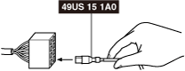 amxzzw00004444
No
Go to the next step.
*7
VERIFY IF MALFUNCTION IS IN WIRING HARNESS (BETWEEN DSC HU/CM POWER SUPPLY AND DSC HU/CM FOR CONTINUITY) OR ELSEWHERE
• Switch the ignition ON.
• Measure the voltage at the DSC HU/CM terminal I (wiring harness-side).
• Is the voltage approx. 12 V?
Yes
Go to the next step.
No
Refer to the wiring diagram and verify whether or not there is a common connector between DSC HU/CM terminal I (wiring harness-side) and ignition switch.
If there is a common connector:
• Determine the malfunctioning part by inspecting the common connector and the terminal for corrosion, damage, or pin disconnection, and the common wiring harness for an open circuit.
• Repair or replace the malfunctioning part.
If there is no common connector:
• Repair or replace the wiring harness which has an open circuit.
*8
VERIFY IF MALFUNCTION IS IN WIRING HARNESS (BETWEEN DSC HU/CM AND GROUND FOR CONTINUITY) OR ELSEWHERE
• Switch the ignition OFF.
• Disconnect the DSC HU/CM connector.
• Inspect for continuity between DSC HU/CM terminal AK (wiring harness-side) and body ground.
• Is there continuity?
Yes
Replace the DSC HU/CM. (open circuit in the DSC HU/CM)
No
Repair or replace the wiring harness for a possible open circuit and poor contact at the ground point, then go to the next step.
9
CONFIRM PCM DTCs
• Retrieve the PCM DTCs using the M-MDS.
• Are any DTCs present?
Yes
Go to the applicable DTC inspection.
No
Go to the next step.
10
VERIFY IF MALFUNCTION CAUSED BY INITIALIZATION PROCEDURE FOR MODULE NOT PERFORMED
• Verify if the malfunction is caused by initialization procedure for the DSC related parts sensor not being performed.
• Has the initial setting for the brake fluid pressure sensor been performed after replacing the DSC HU/CM and SAS control module?
Yes
Go to the next step.
No
Perform the initialization procedure.
11
CONFIRM INSTRUMENT CLUSTER DTC
• Retrieve the instrument cluster DTC using the M-MDS.
• Are any DTCs present?
Yes
Go to the applicable DTC inspection.
No
Replace the instrument cluster.