 |
ac9wzw00004527
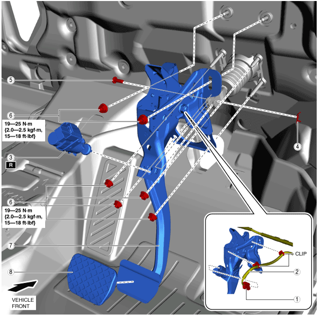
BRAKE PEDAL REMOVAL/INSTALLATION [R.H.D.]
id041100801252
1. Disconnect the negative battery terminal. (See NEGATIVE BATTERY TERMINAL DISCONNECTION/CONNECTION.)
2. Disconnect the brake pipes from the master cylinder. (See MASTER CYLINDER REMOVAL/INSTALLATION [R.H.D.].)
3. Disconnect the vacuum hose from the power brake unit. (See VACUUM HOSE REMOVAL/INSTALLATION [R.H.D.].)
4. Remove in the order indicated in the table.
5. Install in the reverse order of removal.
6. After installation, add brake fluid, bleed the air, and inspect for fluid leakage. (See BRAKE FLUID AIR BLEEDING.)
ac9wzw00004527
|
|
1
|
Brake switch connector
|
|
2
|
Brake switch wiring harness
|
|
3
|
Brake switch
|
|
4
|
Snap pin
(See Snap Pin Installation Note.)
|
|
5
|
Clevis pin
|
|
6
|
Nut
(See Nut Installation Note.)
|
|
7
|
Brake pedal
(See Brake Pedal Removal Note.)
|
|
8
|
Pedal pad
|
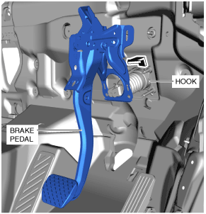
Brake Pedal Removal Note
1. Move the power brake unit to the vehicle front where the power brake unit fork does not interfere with the brake pedal arm.
2. Move the brake pedal in the direction of the arrow shown in the figure, and remove it while avoiding the hook.
ac9wzw00004528
|
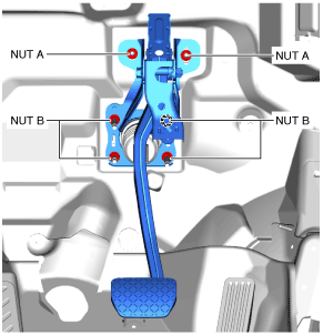
Nut Installation Note
1. Temporarily tighten nuts A.
ac9wzw00004529
|
2. Temporarily tighten nuts B.
3. Tighten nuts B to the specified torque.
4. Tighten nuts A to the specified torque.
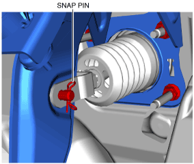
Snap Pin Installation Note
1. Install the snap pin as shown in the figure.
ac9uuw00009695
|
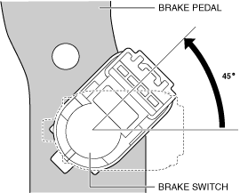
Brake Switch Installation Note
1. Inspect the brake pedal. (See BRAKE PEDAL INSPECTION.)
2. With the brake pedal fully released, insert a new brake switch into the installation hole on the brake pedal.
3. Secure the brake switch by turning it counterclockwise 45°.
ac9wzw00005143
|