 |
am3zzw00012635
OIL PRESSURE SWITCH REMOVAL/INSTALLATION [GW6A-EL, GW6AX-EL]
id0517i2112600
Oil Pressure Switch A
1. Select the selector lever to P position.
2. Disconnect the negative battery terminal. (See NEGATIVE BATTERY TERMINAL DISCONNECTION/CONNECTION.)
3. Remove the front under cover No.2. (See FRONT UNDER COVER No.2 REMOVAL/INSTALLATION.)
4. Clean the transaxle exterior throughout with a steam cleaner or cleaning solvents.
5. Drain the ATF. (See AUTOMATIC TRANSAXLE FLUID (ATF) REPLACEMENT [GW6A-EL, GW6AX-EL].)
6. Remove the oil pan.
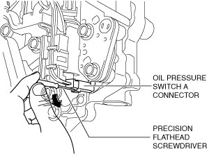
7. Insert a precision flathead screwdriver and move it in the direction of the arrow to disconnect the oil pressure switch A connector as shown in the figure.
am3zzw00012635
|
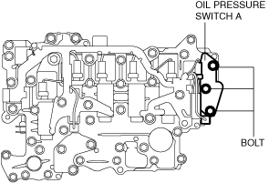
8. Remove the oil pressure switch A fitting bolts.
am3uuw00008720
|
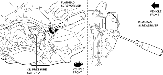
9. Insert a flathead screwdriver as shown in the figure and remove oil pressure switch A from the control valve body while avoiding contact with the oil pan installation surface.
ac30zw00002346
|
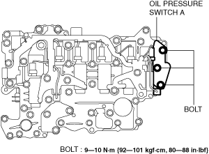
10. Install the oil pressure switch A to the control valve body.
11. Install the oil pressure switch A fitting bolts.
am3zzw00031532
|
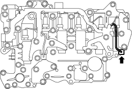
12. Connect the oil pressure switch A connector.
am3uuw00008719
|
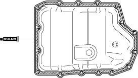
13. Apply a light coat of silicon sealant (TB1217E or equivalent) to the contact surfaces of the oil pan and transaxle case.
am3uuw00008289
|
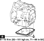
14. Install the oil pan with new bolts before the applied sealant starts to harden.
am3zzw00031534
|
15. Add the ATF. (See AUTOMATIC TRANSAXLE FLUID (ATF) REPLACEMENT [GW6A-EL, GW6AX-EL].)
16. Install the front under cover No.2. (See FRONT UNDER COVER No.2 REMOVAL/INSTALLATION.)
17. Connect the negative battery terminal. (See NEGATIVE BATTERY TERMINAL DISCONNECTION/CONNECTION.)
18. Perform the “Initial Learning” (oil pressure switch A replacement). (See INITIAL LEARNING [GW6A-EL, GW6AX-EL].)
19. Perform the “Mechanical System Test”. (See MECHANICAL SYSTEM TEST [GW6A-EL, GW6AX-EL].)
Oil Pressure Switch B
1. Disconnect the negative battery terminal. (See NEGATIVE BATTERY TERMINAL DISCONNECTION/CONNECTION.)
2. Remove the front under cover No.2. (See FRONT UNDER COVER No.2 REMOVAL/INSTALLATION.)
3. Clean the transaxle exterior throughout with a steam cleaner or cleaning solvents.
4. Drain the ATF. (See AUTOMATIC TRANSAXLE FLUID (ATF) REPLACEMENT [GW6A-EL, GW6AX-EL].)
5. Remove the oil pan.
6. Remove the oil strainer. (See CONTROL VALVE BODY REMOVAL/INSTALLATION [GW6A-EL, GW6AX-EL].)
7. Remove the oil strainer O-ring. (See CONTROL VALVE BODY REMOVAL/INSTALLATION [GW6A-EL, GW6AX-EL].)
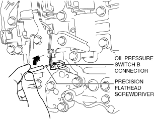
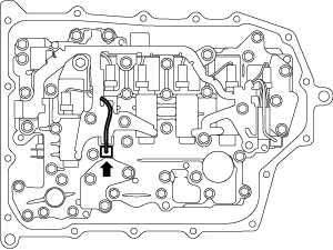
8. Insert a precision flathead screwdriver and move it in the direction of the arrow to disconnect the oil pressure switch B connector as shown in the figure.
ac9wzw00004911
|
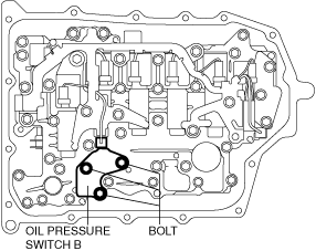
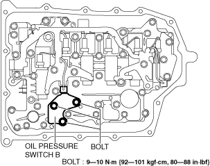
9. Remove the oil pressure switch B.
am3uuw00008722
|
10. Install the oil pressure switch B.
ac8wzw00003337
|
11. Connect the oil pressure switch B connector.
am3uuw00008721
|
12. Install the new oil strainer O-ring. (See CONTROL VALVE BODY REMOVAL/INSTALLATION [GW6A-EL, GW6AX-EL].)
13. Install the new oil strainer. (See CONTROL VALVE BODY REMOVAL/INSTALLATION [GW6A-EL, GW6AX-EL].)
14. Apply a light coat of silicon sealant (TB1217E or equivalent) to the contact surfaces of the oil pan and transaxle case.
am3uuw00008289
|
15. Install the oil pan with new bolts before the applied sealant starts to harden.
am3zzw00031534
|
16. Install the front under cover No.2. (See FRONT UNDER COVER No.2 REMOVAL/INSTALLATION.)
17. Add the ATF. (See AUTOMATIC TRANSAXLE FLUID (ATF) REPLACEMENT [GW6A-EL, GW6AX-EL].)
18. Connect the negative battery terminal. (See NEGATIVE BATTERY TERMINAL DISCONNECTION/CONNECTION.)
19. Perform the “Initial Learning” (oil pressure switch B replacement). (See INITIAL LEARNING [GW6A-EL, GW6AX-EL].)
20. Perform the “Mechanical System Test”. (See MECHANICAL SYSTEM TEST [GW6A-EL, GW6AX-EL].)