CONTROL VALVE BODY REMOVAL/INSTALLATION [GW6A-EL, GW6AX-EL]
id0517i2118000
On-Vehicle Removal
-
Warning
-
• A hot transaxle and ATF can cause severe burns. Turn off the engine and wait until they are cool.
• Using compressed air can cause dirt and other particles to fly out, causing injury to the eyes. Wear protective eyeglasses whenever using compressed air.
-
Caution
-
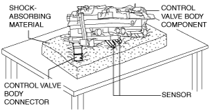
• Placing the control valve body connector side pointed downward could damage the control valve body connector part or sensor. If the servicing can only be performed by pointing the control valve body connector side downward, spread shock-absorbing material, which does not produce dust or foreign matter, and place the control valve body connector part and sensor on the table so that they do not directly contact the table.
1. Select the selector lever to P position.
2. Disconnect the negative battery terminal. (See NEGATIVE BATTERY TERMINAL DISCONNECTION/CONNECTION.)
3. Remove the front under cover No.2. (See FRONT UNDER COVER No.2 REMOVAL/INSTALLATION.)
4. Clean the transaxle exterior throughout with a steam cleaner or cleaning solvents.
5. Remove the air cleaner component. (See INTAKE-AIR SYSTEM REMOVAL/INSTALLATION [SKYACTIV-G 2.5T].)
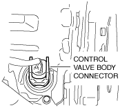
6. Disconnect the control valve body connector.
-
Caution
-
• Make sure that your hand does not touch the terminal as the connector terminal could be damaged.
• Water or foreign matter entering the connector can cause a poor connection or corrosion. Be careful not to allow water droplets or foreign matter to get on the connector when disconnecting it.
7. Remove the hose clamp.
8. Drain the ATF. (See AUTOMATIC TRANSAXLE FLUID (ATF) REPLACEMENT [GW6A-EL, GW6AX-EL].)
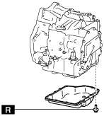
9. Remove the oil pan.
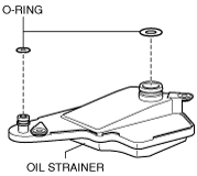
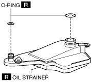
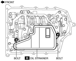
10. Remove the oil strainer.
11. Remove the oil strainer O-ring.
12. Remove the control valve body.
-
Caution
-
• Remove the control valve body directly from underneath so that force is not applied to the control valve body connector in the lateral direction.
• When removing the control valve body component for vehicles with oil cooler No.2, be careful not to loose the spool valve and the spool valve spring because they may fall off.
13. Remove the oil seal (control valve body). (See OIL SEAL (CONTROL VALVE BODY) REPLACEMENT [GW6A-EL, GW6AX-EL].)
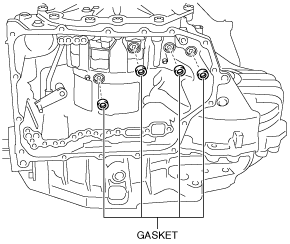
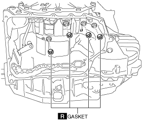
14. Remove the gasket from the transaxle case.
On-Vehicle Installation (With Oil Cooler No.2)
1. Install the gasket to the transaxle case.
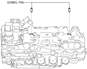
2. Install the dowel pin to the control valve body.
-
Note
-
• Oil with a color different from the genuine ATF may be adhered to a new control valve body.
• If the dowel pin remains in the transaxle case, remove the dowel pin from the transaxle case and install the dowel pin to the control valve body.
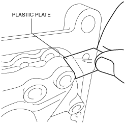
3. Prepare a plastic plate of the size indicated in the figure.
-
Note
-
• Use a plastic plate made of material that is not too hard.
-
A: 20 mm {0.79 in}
B: ?8 mm {0.3 in}
C: 15 mm {0.59 in}
D: 65 mm {2.6 in}
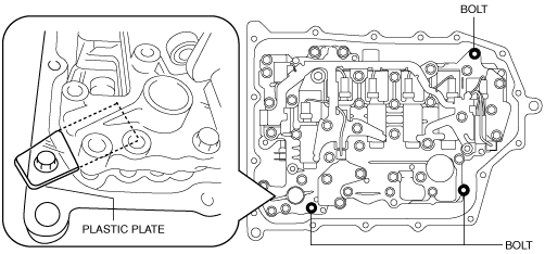
4. Insert the spool valve and the spool valve spring into the transaxle case, and hold the relief valve and the spring using the plastic plate prepared in Step 3 as shown in the figure so that they do not fall off.
5. Install the control valve body using the following procedure.
-
Caution
-
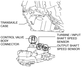
• Install the control valve body so that the turbine/input shaft speed sensor, output shaft speed sensor, and control valve body connector do not contact the transaxle case.
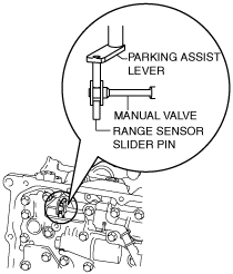
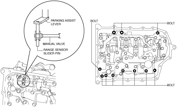
- (1) Engage the parking assist lever component on both surfaces of the manual valve.
-
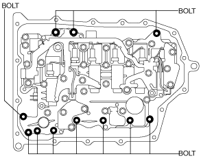
- (2) Temporarily install the control valve body installation bolts at three locations so that the plastic plate installed in Step 4 can be removed.
-
- (3) Remove the plastic plate.
-
-
Caution
-
• Because the control valve body may be damaged if foreign material penetrates it, carefully remove the plastic plate preventing foreign material from penetrating the control valve body.
- (4) Install the control valve body.
-
-
Tightening torque
-
9—10 N·m {92—101 kgf·cm, 80—88 in·lbf}
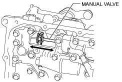
6. Move the manual valve in both directions of the arrow and verify that the manual valve is correctly connected to the parking assist lever component and the slider pin for the range sensor.
-
Note
-
• If the manual valve only moves in the gap between the parking assist lever component surface and the manual valve surface, the manual valve and the parking assist lever component are correctly engaged.
7. Install the new oil strainer O-ring.
8. Install the new oil strainer.
-
Tightening torque
-
9—10 N·m {92—101 kgf·cm, 80—88 in·lbf}
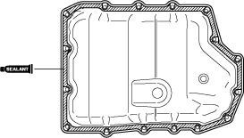
9. Apply a light coat of silicon sealant (TB1217E or equivalent) to the contact surfaces of the oil pan and transaxle case.
-
Caution
-
• Clean any remaining silicone sealant on the contact surface of the transaxle case and oil pan, and degrease the sealant area. Otherwise, oil could leak.
10. Install the oil pan with new bolts before the applied sealant starts to harden.
-
Tightening torque
-
8—10 N·m {82—101 kgf·cm, 71—88 in·lbf}
11. Install the front under cover No.2. (See FRONT UNDER COVER No.2 REMOVAL/INSTALLATION.)
12. Install the oil seal (control valve body). (See OIL SEAL (CONTROL VALVE BODY) REPLACEMENT [GW6A-EL, GW6AX-EL].)
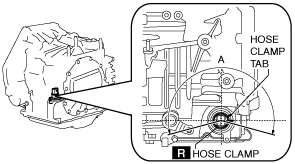
13. Install a new hose clamp to the position shown in the figure.
-
Caution
-
• If the hose clamp is reused it could cause ATF leakage, therefore use a new hose clamp.
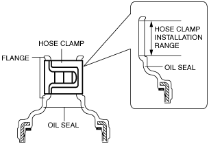
• Install the hose clamp tab to within the range shown in the figure.
A: 210°
• Install the hose clamp so that it does not interfere with the top and bottom flanges of the oil seal to maintain the waterproofing integrity.
14. Connect the control valve body connector.
-
Caution
-
• Make sure that your hand does not touch the terminal as the connector terminal could be damaged.
• Verify that there is no fluid or foreign matter adhering to the connector before connecting the connector.
• Insert the connector straight as the connector terminal could be damaged.
• Rotate the connector lever until a click is heard.
15. Add the ATF. (See AUTOMATIC TRANSAXLE FLUID (ATF) REPLACEMENT [GW6A-EL, GW6AX-EL].)
16. Install the air cleaner component. (See INTAKE-AIR SYSTEM REMOVAL/INSTALLATION [SKYACTIV-G 2.5T].)
17. Connect the negative battery terminal. (See NEGATIVE BATTERY TERMINAL DISCONNECTION/CONNECTION.)
18. Perform the “TCM configuration” (Control valve body Replacement). (See TCM CONFIGURATION [GW6A-EL, GW6AX-EL].)
-
Caution
-
• The transaxle does not operate normally if the TCM configuration is not performed. When the control valve body is replaced, always perform the TCM configuration to enable the transaxle to operate normally.
• When the control valve body is replaced, a U-code DTC is output. After completing the TCM configuration, clear the U-code DTC and verify that no DTCs are output.
19. Delete the U code and verify that no DTC is output. (See ON-BOARD DIAGNOSTIC SYSTEM DTC INSPECTION [TCM (GW6A-EL, GW6AX-EL)].)
20. Perform the “Initial Learning” (Control valve body Replacement). (See INITIAL LEARNING [GW6A-EL, GW6AX-EL].)
21. Perform the “Mechanical System Test”. (See MECHANICAL SYSTEM TEST [GW6A-EL, GW6AX-EL].)
22. Perform the “Road Test”. (See ROAD TEST [GW6A-EL, GW6AX-EL].)
On-Vehicle Installation (Without Oil Cooler No.2)
1. Install the gasket to the transaxle case.
2. Install the dowel pin to the control valve body.
-
Note
-
• Oil with a color different from the genuine ATF may be adhered to a new control valve body.
• If the dowel pin remains in the transaxle case, remove the dowel pin from the transaxle case and install the dowel pin to the control valve body.
3. Install the control valve body so that the parking assist lever component is engaged in the gap between the two surfaces of the spool part of the manual valve.
-
Caution
-
• Install the control valve body so that the turbine/input shaft speed sensor, output shaft speed sensor, and control valve body connector do not contact the transaxle case.
-
Tightening torque
-
9—10 N·m {92—101 kgf·cm, 80—88 in·lbf}
4. Move the manual valve in both directions of the arrow and verify that the manual valve is correctly connected to the parking assist lever component and the slider pin for the range sensor.
-
Note
-
• If the manual valve only moves in the gap between the parking assist lever component surface and the manual valve surface, the manual valve and the parking assist lever component are correctly engaged.
5. Install the new oil strainer O-ring.
6. Install the new oil strainer.
-
Tightening torque
-
9—10 N·m {92—101 kgf·cm, 80—88 in·lbf}
7. Apply a light coat of silicon sealant (TB1217E or equivalent) to the contact surfaces of the oil pan and transaxle case.
-
Caution
-
• Clean any remaining silicone sealant on the contact surface of the transaxle case and oil pan, and degrease the sealant area. Otherwise, oil could leak.
8. Install the oil pan with new bolts before the applied sealant starts to harden.
-
Tightening torque
-
8—10 N·m {82—101 kgf·cm, 71—88 in·lbf}
9. Install the front under cover No.2. (See FRONT UNDER COVER No.2 REMOVAL/INSTALLATION.)
10. Install the oil seal (control valve body). (See OIL SEAL (CONTROL VALVE BODY) REPLACEMENT [GW6A-EL, GW6AX-EL].)
11. Install a new hose clamp to the position shown in the figure.
-
Caution
-
• If the hose clamp is reused it could cause ATF leakage, therefore use a new hose clamp.
• Install the hose clamp tab to within the range shown in the figure.
A: 210°
• Install the hose clamp so that it does not interfere with the top and bottom flanges of the oil seal to maintain the waterproofing integrity.
12. Connect the control valve body connector.
-
Caution
-
• Make sure that your hand does not touch the terminal as the connector terminal could be damaged.
• Verify that there is no fluid or foreign matter adhering to the connector before connecting the connector.
• Insert the connector straight as the connector terminal could be damaged.
• Rotate the connector lever until a click is heard.
13. Add the ATF. (See AUTOMATIC TRANSAXLE FLUID (ATF) REPLACEMENT [GW6A-EL, GW6AX-EL].)
14. Install the air cleaner component. (See INTAKE-AIR SYSTEM REMOVAL/INSTALLATION [SKYACTIV-G 2.5T].)
15. Connect the negative battery terminal. (See NEGATIVE BATTERY TERMINAL DISCONNECTION/CONNECTION.)
16. Perform the “TCM configuration” (Control valve body Replacement). (See TCM CONFIGURATION [GW6A-EL, GW6AX-EL].)
-
Caution
-
• The transaxle does not operate normally if the TCM configuration is not performed. When the control valve body is replaced, always perform the TCM configuration to enable the transaxle to operate normally.
• When the control valve body is replaced, a U-code DTC is output. After completing the TCM configuration, clear the U-code DTC and verify that no DTCs are output.
17. Delete the U code and verify that no DTC is output. (See ON-BOARD DIAGNOSTIC SYSTEM DTC INSPECTION [TCM (GW6A-EL, GW6AX-EL)].)
18. Perform the “Initial Learning” (Control valve body Replacement). (See INITIAL LEARNING [GW6A-EL, GW6AX-EL].)
19. Perform the “Mechanical System Test”. (See MECHANICAL SYSTEM TEST [GW6A-EL, GW6AX-EL].)
20. Perform the “Road Test”. (See ROAD TEST [GW6A-EL, GW6AX-EL].)