STEERING GEAR AND LINKAGE INSPECTION
id061300802000
1. Remove the steering gear and linkage. (See STEERING GEAR AND LINKAGE REMOVAL/INSTALLATION.)
2. Remove the tie-rod end and boot. (See STEERING GEAR AND LINKAGE DISASSEMBLY.)
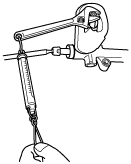
3. Measure the rotation torque of the pinion shaft using a crescent wrench and pull scale. (speed measurement reference 5 rpm)
- (1) Install the crescent wrench to the steering gear.
-
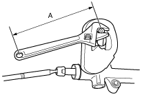
- (2) Measure the length from the pinion shaft center to the crescent wrench end (application point of pull scale) as shown in the figure. This is dimension A.
-
- (3) The rotation torque of the pinion shaft can be calculated using the following formula.
- Pinion shaft rotation torque (N·m {kgf·cm, in·lbf}) = Pull scale reading (N {kgf, lbf}) × A (m {cm, in})
-
Pinion shaft rotation torque (center of rack ± 180°)
-
0.9—1.5 N·m {9.2—15 kgf·cm, 8.0—13 in·lbf}
-