 |
ac9wzw00005554
CLOCK SPRING REMOVAL/INSTALLATION
id081000802000
1. Switch the ignition ON (engine off or on).
2. Open the driver's door.
3. Switch the ignition off.
4. Disconnect the negative battery terminal and wait for 1 min or more. (See NEGATIVE BATTERY TERMINAL DISCONNECTION/CONNECTION.)
5. Remove the following parts:
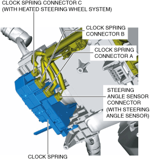
6. Disconnect the clock spring connector A. (See Clock Spring Connector A Disconnect Note.)
ac9wzw00005554
|
7. Disconnect the clock spring connector B.
8. Disconnect the clock spring connector C. (with heated steering wheel system)
9. Disconnect the steering angle sensor connector. (with steering angle sensor)
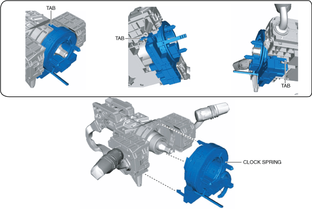
10. Remove the tabs as shown in the figure and remove the clock spring.
ac9uuw00009157
|
11. Install in the reverse order of removal. (See Clock Spring Installation Note.)
12. Switch the ignition ON (engine off or on).
13. Verify that the air bag/seat belt pre-tensioner system warning light illuminates for approx. 6 s and turns off.
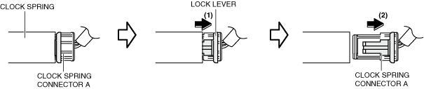
Clock Spring Connector A Disconnect Note
1. Pull out the clock spring connector A lock lever in the direction of arrow (1) shown in the figure.
ac9uuw00009158
|
2. Move the clock spring connector A in the direction of arrow (2) shown in the figure to disconnect it.
Clock Spring Installation Note