LIFTGATE ADJUSTMENT
id091100521400
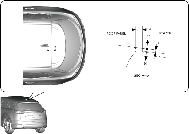
1. Measure the gap and height difference between the liftgate and the roof panel.
-
Standard clearance
-
a: 5.0—7.0 mm {0.20—0.27 in}
b: –2.7—–0.7 mm {–0.10—–0.03 in}
-
• If the measured value exceeds the standard clearance, adjust the liftgate using the following procedure:
-
3. Verify that the gap and height difference between the liftgate and the roof panel is within the specification.
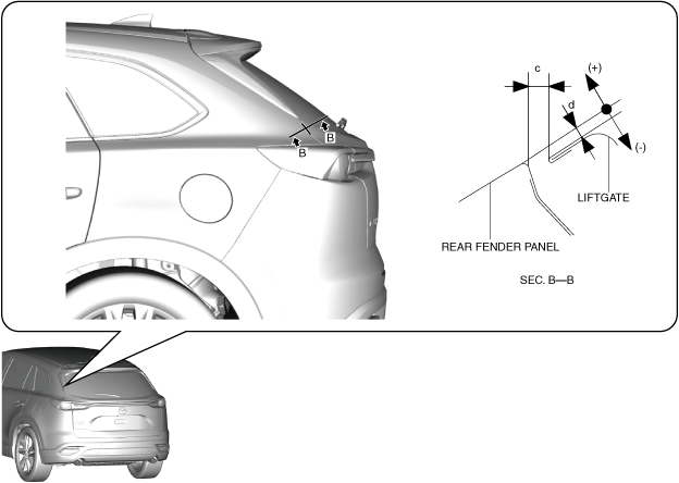
2. Measure the gap and height difference between the liftgate and the rear fender panel.
-
Standard clearance
-
c: 3.5—7.5 mm {0.14—0.29 in}
d: –2.3—1.7 mm {–0.090—0.066 in}
-
• If the measured value exceeds the standard clearance, adjust the liftgate using the following procedure:
-
3. Verify that the gap and height difference between the liftgate and the rear fender panel is within the specification.
4. Verify that the liftgate opens/closes smoothly.
-
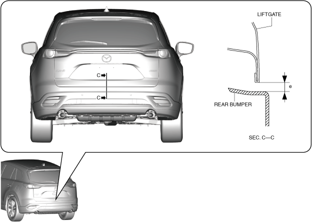
3. Measure the gap between the liftgate and the rear bumper.
-
Standard clearance (With power liftgate (PLG) system)
-
e: 3.6—7.6 mm {0.15—0.29 in}
-
Standard clearance (Without power liftgate (PLG) system)
-
e: 4.0—8.0 mm {0.16—0.31 in}
-
• If the measured value exceeds the standard clearance, adjust the liftgate using the following procedure:
-
3. Verify that the gap between the liftgate and the rear bumper is within the specification.
4. Spray or pour water on the liftgate and surrounding area using a hose or high pressure water pressure car wash and verify that there is no water leakage.
5. Perform the 360° view monitor system aiming. (with 360° view monitor system) (See 360°VIEW MONITOR SYSTEM AIMING.)
6. Perform the parking assist system initialization (calibration). (with projected vehicle path line display and without 360° view monitor system) (See PARKING ASSIST SYSTEM INITIALIZATION (CALIBRATION).)