 |
ac9uuw00009338
LIFTGATE LOCK ACTUATOR INSPECTION
id091400512100
1. Disconnect the negative battery terminal. (See NEGATIVE BATTERY TERMINAL DISCONNECTION/CONNECTION.)
2. Remove the following parts:
3. Liftgate latch and lock actuator. (See LIFTGATE LATCH AND LOCK ACTUATOR REMOVAL/INSTALLATION.)
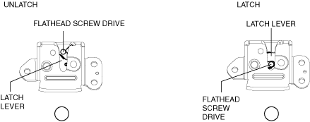
4. Press in the latch lever of the liftgate latch and lock actuator using a flathead screwdriver, and set it to the latched condition.
ac9uuw00009338
|
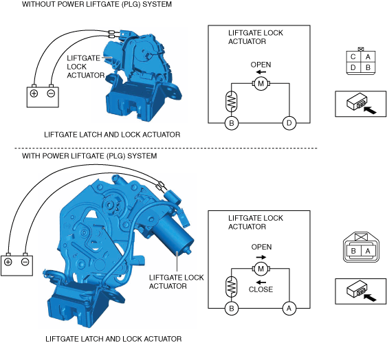
5. Connect terminal D (Without power liftgate (PLG) system)/B (With power liftgate (PLG) system) to the positive battery voltage, connect terminal B (Without power liftgate (PLG) system)/A (With power liftgate (PLG) system) to the ground, and verify that the latch lever is released and the condition changes to the unlatch condition.
ac9uuw00009339
|