 |
am2zzw00011504
BLIND SPOT MONITORING (BSM) CONTROL MODULE INSPECTION
id152000003600
1. Disconnect the negative battery terminal. (See NEGATIVE BATTERY TERMINAL DISCONNECTION/CONNECTION.)
2. Remove the following parts:
3. Connect the negative battery terminal. (See NEGATIVE BATTERY TERMINAL DISCONNECTION/CONNECTION.)
4. Verify that the voltages of each of the terminals are as indicated in the terminal voltage table (reference).
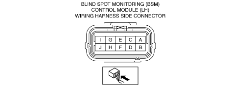
Terminal Voltage Table (Reference)
Blind spot monitoring (BSM) control module (LH)
am2zzw00011504
|
|
Terminal |
Signal name |
Connected to |
Measurement conditions |
Voltage (V) |
Inspection item(s) |
|
|---|---|---|---|---|---|---|
|
A
|
Local CAN_H
|
Blind spot monitoring (BSM) control module (RH)
|
Because this terminal is for communication, determination using terminal voltage inspection is not possible.
|
|||
|
B
|
Local CAN_L
|
Blind spot monitoring (BSM) control module (RH)
|
Because this terminal is for communication, determination using terminal voltage inspection is not possible.
|
|||
|
C
|
MS-CAN_H
|
Data link connector-2
|
Because this terminal is for communication, determination using terminal voltage inspection is not possible.
|
|||
|
D
|
MS-CAN_L
|
Data link connector-2
|
Because this terminal is for communication, determination using terminal voltage inspection is not possible.
|
|||
|
E
|
—
|
—
|
—
|
—
|
—
|
|
|
F
|
—
|
—
|
—
|
—
|
—
|
|
|
G
|
Blind spot monitoring (BSM) warning light signal (LH)
|
Blind spot monitoring (BSM) warning light (LH)
|
Using the simulation function WRN_IND_L for the blind spot monitoring system, turn off the blind spot monitoring (BSM) warning light.
|
1.0 or less
|
• Blind spot monitoring (BSM) warning light (LH)
• Related wiring harness
|
|
|
Using the simulation function WRN_IND_L for the blind spot monitoring system, turn on the blind spot monitoring (BSM) warning light.
|
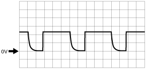
Wave pattern (See Pattern 1.)
|
|||||
|
H
|
—
|
—
|
—
|
—
|
—
|
|
|
I
|
Power position (IG1)
|
IG1 relay
|
Ignition switched ON (engine off or on)
|
VB
|
• C/U IG1 15A fuse
• IG1 relay
• Related wiring harness
|
|
|
Ignition switched off or ACC
|
1.0 or less
|
|||||
|
J
|
Ground
|
Body ground
|
Under any condition
|
1.0 or less
|
Related wiring harness
|
|
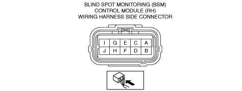
Blind spot monitoring (BSM) control module (RH)
am2zzw00011505
|
|
Terminal |
Signal name |
Connected to |
Measurement conditions |
Voltage (V) |
Inspection item(s) |
|
|---|---|---|---|---|---|---|
|
A
|
Local CAN_H
|
Blind spot monitoring (BSM) control module (LH)
|
Because this terminal is for communication, determination using terminal voltage inspection is not possible.
|
|||
|
B
|
Local CAN_L
|
Blind spot monitoring (BSM) control module (LH)
|
Because this terminal is for communication, determination using terminal voltage inspection is not possible.
|
|||
|
C
|
—
|
—
|
—
|
—
|
—
|
|
|
D
|
—
|
—
|
—
|
—
|
—
|
|
|
E
|
—
|
—
|
—
|
—
|
—
|
|
|
F
|
—
|
—
|
—
|
—
|
—
|
|
|
G
|
Blind spot monitoring (BSM) warning light signal (RH)
|
Blind spot monitoring (BSM) warning light (RH)
|
Using the simulation function WRN_IND_R for the blind spot monitoring system, turn off the blind spot monitoring (BSM) warning light.
|
1.0 or less
|
• Blind spot monitoring (BSM) warning light (RH)
• Related wiring harness
|
|
|
Using the simulation function WRN_IND_R for the blind spot monitoring system, turn on the blind spot monitoring (BSM) warning light.
|
Wave pattern (See Pattern 1.)
|
|||||
|
H
|
—
|
—
|
—
|
—
|
—
|
|
|
I
|
Power position (IG1)
|
IG relay
|
Ignition switched ON (engine off or on)
|
B+
|
• C/U IG1 15A fuse
• IG1 relay
• Related wiring harness
|
|
|
Ignition switched off or ACC
|
1.0 or less
|
|||||
|
J
|
Ground
|
Body ground
|
Under any condition
|
1.0 or less
|
Related wiring harness
|
|
Inspection Using an Oscilloscope (Reference)
Pattern 1
adejjw00011272
|