LASER SENSOR INSPECTION
id152000015200
Simple Inspection
-
Warning
-
• To prevent eye injury, do not peer directly into the laser sensor using optical instruments with a magnification function such as magnifying glasses or microscopic and objective lenses within a distance of 100 mm {3.94 in} from the sensor.
• Because a simple reflector held with a hand is required, if heavy material such as a steel plate is used, it could be dropped resulting in an accident. Therefore, use light materials such as a plastic plate or cardboard when making the reflector.
-
Caution
-
• Perform the work in an area where 6 m {20 ft} or more of space from the front of the vehicle is available.
• Remove cargo from the cabin and trunk compartment so that the vehicle is in an unloaded condition.
• Adjust the air pressure of each tire to the specified value.
-
Note
-
• If there is fogging or water droplets on the black-colored print area (near-infrared laser emitting part) in the upper center area of the windshield, the laser sensor may operate incorrectly and the inspection may not be done correctly. If this occurs, clear the fogging or remove water droplets using the following methods.
If there is fogging or water droplets on the exterior side of the windshield:
-
? Operate the windshield wipers to clear the fogging and remove the water droplets.
If there is fogging on the interior side of the windshield:
-
? Operate the air conditioner defroster to remove the fogging on the area where the laser sensor is installed. (Fogging can easily occur when the ambient temperature is low, humidity is high, or there is a large difference between the temperature inside and outside of the vehicle.)
1. To make the simple reflector, overlap three pieces of commercially available aluminum foil and adhere them to a plastic plate or piece of cardboard with a length of 50 cm {20 in} or more on one side.
-
Note
-
• If two or fewer pieces of aluminum foil are used, near-infrared reflection may weaken and the M-MDS will be unable to measure the correct distance.
• A reflective material or material which facilitates near-infrared light reflection can be substituted for the aluminum foil.
2. Park the vehicle on level ground.
3. Connect the M-MDS to the DLC-2.
4. After vehicle identification, the following can be selected from the M-MDS initialization screen.
- (1) “Data logger”
-
- (2) “Module”
-
- (3) “SCBS”
-
5. Select “DST_BMP_TGT” from PID/DATA Monitor Table.
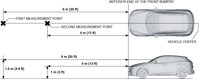
6. Stand at the position 6 m {20 ft} from the front end of the front bumper and hold the simple reflector made in Step 1 at a height of 1.5 m {4.9 ft} from the ground to verify that the M-MDS screen display is at 6 m {20 ft}.
7. Then, move to the position 4 m {13 ft} from the front end of the front bumper and hold the simple reflector at a height of 1 m {3 ft} from the ground to verify that the M-MDS screen display is at 4 m {13 ft}.
-
Note
-
• The brand emblem of the front bumper indicates the center position at the rear of the vehicle.
• The “DST_BMP_TGT” monitoring value is displayed in 1 m {3 ft} increments.
8. If there is a malfunction, verify that there is no damage with the laser sensor tab and in the laser sensor installation area of the windshield. (See LASER SENSOR REMOVAL/INSTALLATION.)
-