 |
ac9uuw00009490
EXHAUST SYSTEM REMOVAL/INSTALLATION [SKYACTIV-G 2.5T]
id0115q4800200
Exhaust System Removal/Installation (2WD)
1. Disconnect the negative battery terminal. (See NEGATIVE BATTERY TERMINAL DISCONNECTION/CONNECTION.)
2. Remove in the order indicated in the table.
3. Remove the insulator. (See Exhaust System Insulator Removal/Installation (2WD).)
4. Install in the reverse order of removal.
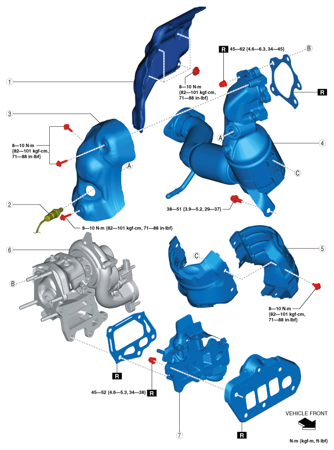
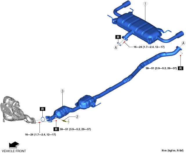
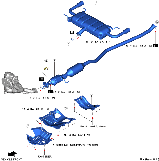
Step 1
ac9uuw00009490
|
|
1
|
Main silencer
|
|
2
|
Plate
|
|
3
|
Brace bar
(See Brace bar removal note (2WD).)
|
|
4
|
Tunnel member
|
|
5
|
HO2S
|
|
6
|
TWC
|
Step 2
ac9wzw00005878
|
|
1
|
Insulator No.1
|
|
2
|
A/F sensor
|
|
3
|
Insulator No.2
|
|
4
|
WU-TWC
|
|
5
|
Insulator No.3
|
|
6
|
Dynamic pressure turbo
|
|
7
|
Exhaust manifold
|
Brace bar removal note (2WD)
1. Remove the floor under cover. (See FLOOR UNDER COVER REMOVAL/INSTALLATION.)
2. Remove the brace bar.
Insulator No.1 removal note (2WD)
1. Remove the plug hole plate. (See PLUG HOLE PLATE REMOVAL/INSTALLATION [SKYACTIV-G 2.5T].)
2. Remove the cowl panel. (See COWL PANEL REMOVAL/INSTALLATION.)
3. Remove the front under cover No.2. (See FRONT UNDER COVER No.2 REMOVAL/INSTALLATION.)
4. Remove the front crossmember. (R.H.D.) (See FRONT CROSSMEMBER REMOVAL/INSTALLATION.)
5. Remove the insulator No.1.
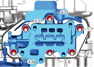
Exhaust manifold installation note (2WD)
1. Tighten the nuts in the order shown in the figure.
ac9uuw00009492
|
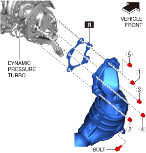
WU-TWC installation note (2WD)
1. Temporarily tighten the WU-TWC installation nuts.
2. Tighten the WU-TWC installation nuts in the order shown in the figure to the specified torque.
ac9uuw00009493
|
3. Temporarily tighten the WU-TWC installation bolt.
4. Tighten the WU-TWC installation bolt to the specified torque.
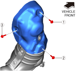
Insulator No.2 installation note (2WD)
1. Tighten the bolts in the order shown in the figure.
ac9uuw00009494
|
Insulator No.1 installation note (2WD)
1. Install the insulator No.1.
2. Install the front under cover No.2. (See FRONT UNDER COVER No.2 REMOVAL/INSTALLATION.)
3. Install the cowl panel. (See COWL PANEL REMOVAL/INSTALLATION.)
4. Install the plug hole plate. (See PLUG HOLE PLATE REMOVAL/INSTALLATION [SKYACTIV-G 2.5T].)
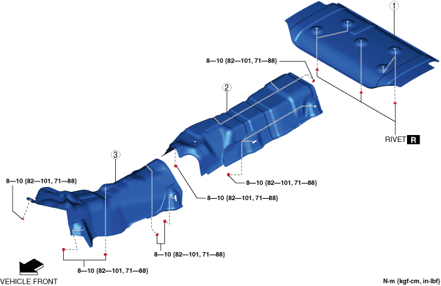
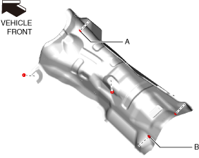
Tunnel member installation note (2WD)
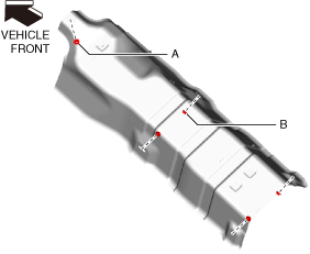
1. Tighten bolt A shown in the figure to the specified torque.
ac9uuw00009495
|
2. Tighten bolt B shown in the figure to the specified torque.
3. Tighten the remaining bolts to the specified torque.
Brace bar installation note (2WD)
1. Tighten bolt A shown in the figure to the specified torque.
ac9uuw00009496
|
2. Tighten bolt B shown in the figure to the specified torque.
3. Tighten the remaining bolts to the specified torque.
4. Install the floor under cover. (See FLOOR UNDER COVER REMOVAL/INSTALLATION.)
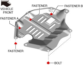
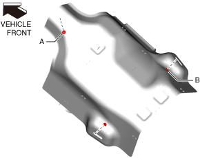
Plate installation note (2WD)
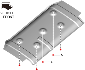
1. Install fastener A shown in the figure.
ac9uuw00009497
|
2. Install fastener B shown in the figure.
3. Install the remaining fasteners.
4. Tighten the bolts shown in the figure to the specified torque.
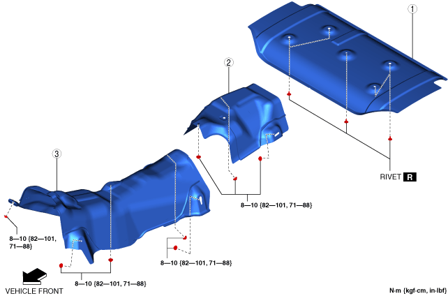
Exhaust System Insulator Removal/Installation (2WD)
1. Remove in the order indicated in the table.
2. Install in the reverse order of removal.
ac9uuw00009506
|
|
1
|
Insulator (rear)
|
|
2
|
Insulator (middle)
|
|
3
|
Insulator (front)
|
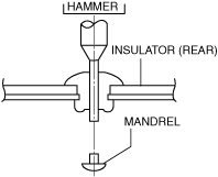
Insulator (rear) removal note (2WD)
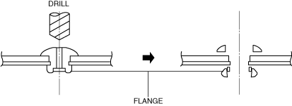
1. Push out the mandrel using a hammer and punch (2—2.8 mm {0.08—0.11 in} diameter).
ac5uuw00000434
|
2. Remove the flange using a drill (5 mm {0.20 in} drill bit).
ar8uuw00001479
|
Insulator (front) installation note (2WD)
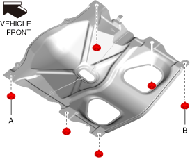
1. Tighten nut A shown in the figure to the specified torque.
ac9uuw00009499
|
2. Tighten nut B shown in the figure to the specified torque.
3. Tighten the remaining nuts to the specified torque.
Insulator (middle) installation note (2WD)
1. Tighten nut A shown in the figure to the specified torque.
ac9uuw00009500
|
2. Tighten nut B shown in the figure to the specified torque.
3. Tighten the remaining nuts to the specified torque.
Insulator (rear) installation note (2WD)
1. Install rivets A shown in the figure.
ac9uuw00009501
|
2. Install the remaining rivets.
Exhaust System Removal/Installation (4WD)
1. Disconnect the negative battery terminal. (See NEGATIVE BATTERY TERMINAL DISCONNECTION/CONNECTION.)
2. Remove in the order indicated in the table.
3. Remove the insulator. (See Exhaust System Insulator Removal/Installation (4WD).)
4. Install in the reverse order of removal.
Step 1
ac9uuw00009504
|
|
1
|
Main silencer
|
|
2
|
HO2S
|
|
3
|
TWC
|
Step 2
ac9wzw00005878
|
|
1
|
Insulator No.1
|
|
2
|
A/F sensor
|
|
3
|
Insulator No.2
|
|
4
|
WU-TWC
|
|
5
|
Insulator No.3
|
|
6
|
Dynamic pressure turbo
|
|
7
|
Exhaust manifold
|
Insulator No.1 removal note (4WD)
1. Remove the plug hole plate. (See PLUG HOLE PLATE REMOVAL/INSTALLATION [SKYACTIV-G 2.5T].)
2. Remove the cowl panel. (See COWL PANEL REMOVAL/INSTALLATION.)
3. Remove the front crossmember. (See FRONT CROSSMEMBER REMOVAL/INSTALLATION.)
4. Remove the insulator No.1.
Exhaust manifold installation note (4WD)
1. Tighten the nuts in the order shown in the figure.
ac9uuw00009492
|
WU-TWC installation note (4WD)
1. Temporarily tighten the WU-TWC installation nuts.
2. Tighten the WU-TWC installation nuts in the order shown in the figure to the specified torque.
ac9uuw00009493
|
3. Temporarily tighten the WU-TWC installation bolt.
4. Tighten the WU-TWC installation bolt to the specified torque.
Insulator No.2 installation note (4WD)
1. Tighten the bolts in the order shown in the figure.
ac9uuw00009494
|
Insulator No.1 installation note (4WD)
1. Install the insulator No.1.
2. Install the front crossmember. (See FRONT CROSSMEMBER REMOVAL/INSTALLATION.)
3. Install the cowl panel. (See COWL PANEL REMOVAL/INSTALLATION.)
4. Install the plug hole plate. (See PLUG HOLE PLATE REMOVAL/INSTALLATION [SKYACTIV-G 2.5T].)
Exhaust System Insulator Removal/Installation (4WD)
1. Remove the propeller shaft. (See PROPELLER SHAFT REMOVAL/INSTALLATION.)
2. Remove in the order indicated in the table.
3. Install in the reverse order of removal.
ac9wzw00004654
|
|
1
|
Insulator (rear)
|
|
2
|
Insulator (middle)
|
|
3
|
Insulator (front)
|
Insulator (rear) removal note (4WD)
1. Push out the mandrel using a hammer and punch (2—2.8 mm {0.08—0.11 in} diameter).
ac5uuw00000434
|
2. Remove the flange using a drill (5 mm {0.20 in} drill bit).
ar8uuw00001479
|
Insulator (front) installation note (4WD)
1. Tighten nut A shown in the figure to the specified torque.
ac9uuw00009349
|
2. Tighten nut B shown in the figure to the specified torque.
3. Tighten the remaining nuts to the specified torque.
Insulator (middle) installation note (4WD)
1. Tighten nut A shown in the figure to the specified torque.
ac9uuw00009354
|
2. Tighten nut B shown in the figure to the specified torque.
3. Tighten the remaining nut to the specified torque.
Insulator (rear) installation note (4WD)
1. Install rivets A shown in the figure.
ac9uuw00009351
|
2. Install the remaining rivets.